ALLPCB


Introduction
As living standards improve, health issues have received greater attention, especially cardiac conditions. From large hospital equipment to portable instruments and remote diagnostic devices, development has advanced rapidly. All ECG devices rely on accurate acquisition of cardiac signals. Large systems impose strict performance requirements on the acquisition circuitry, resulting in complex and bulky circuit design. Portable devices require a balance of performance and compact size. Under the project for a portable automatic ECG diagnostic system, a portable ECG signal acquisition circuit was designed.
1 ECG generation mechanism
The sinoatrial node emits an excitation that propagates along specific pathways and timing through the atria and ventricles, causing the heart to depolarize and repolarize in an ordered sequence. During each cardiac cycle, the direction, pathway, order, and timing of these bioelectrical changes follow a regular pattern. These bioelectric changes are transmitted to the body surface via conductive tissues and body fluids, producing periodic electrical potential changes at various body locations, i.e. the cardiac potential. Placing electrodes at specific locations on the body surface and recording the cardiac potential over time produces the conventional electrocardiogram (ECG).
2 System architecture
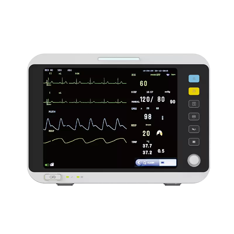
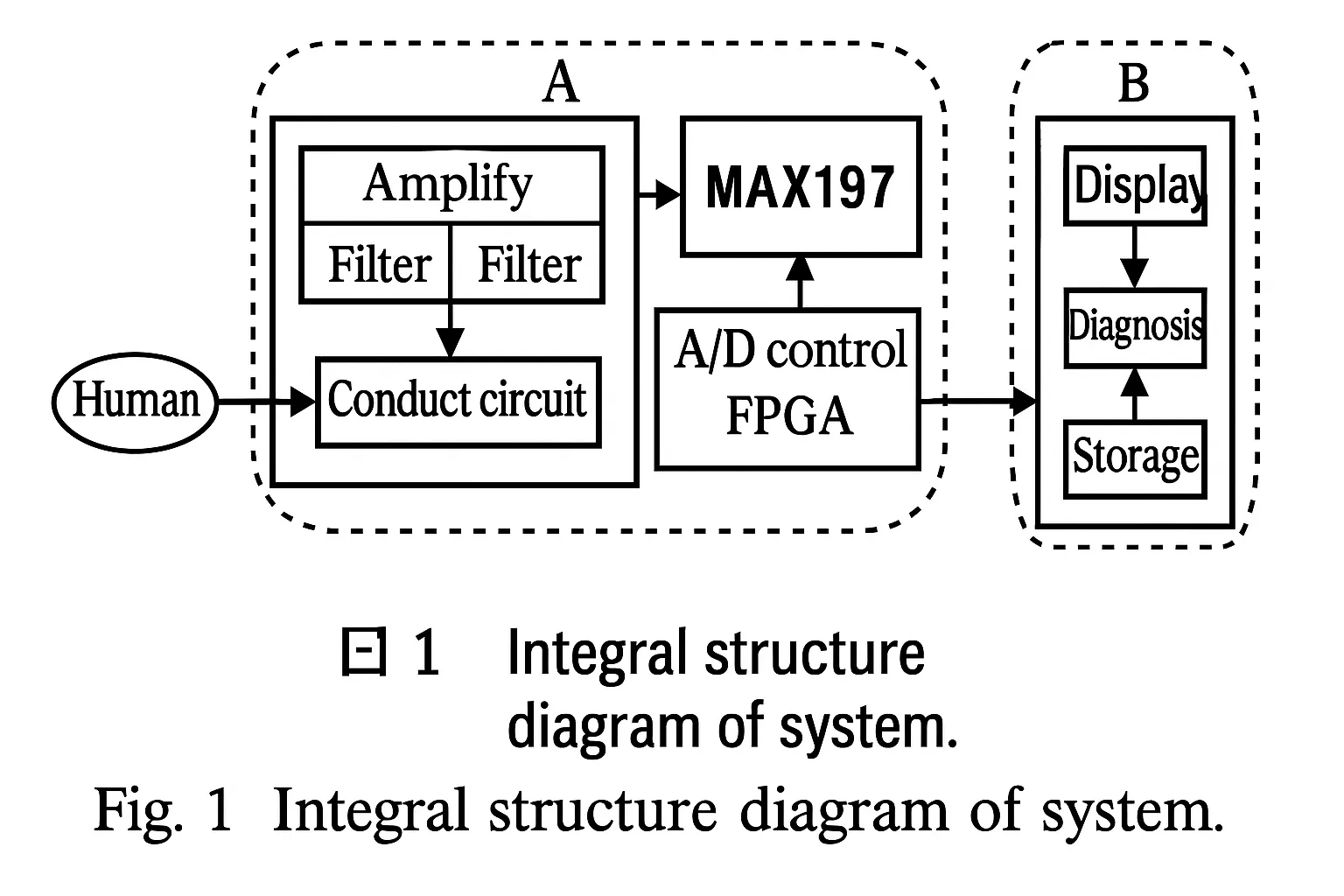
The goal of the portable ECG monitor is to provide automatic cardiac diagnosis while being convenient for home and travel use. This article focuses on the device front end: the signal acquisition and processing section. ECG acquisition is mainly performed by analog circuits for amplification and filtering. Under FPGA control, the signals are digitized for subsequent processing and storage. The overall system structure is shown in Figure 1.
3 ECG signal acquisition
3.1 ECG signal characteristics
Normal ECG amplitudes range from 10 V ~ 4 mV, with a typical value near 1 mV. Frequency content is between 0.05 Hz and 100 Hz, with 90% of energy concentrated between 0.25 Hz and 35 Hz. When detecting these weak signals, noise suppression is critical. Major noise sources include electrode polarization voltages at the skin-electrode interface, contamination from other physiological signals, electronic device noise, radio-frequency interference, and mains interference.
Given the weak nature of ECG signals, the front-end amplifier should offer high input impedance, high common-mode rejection ratio (CMRR), low noise, and low drift.
Considering these requirements, the chosen amplifier is the AD620. The AD620 has an input impedance of 10 GΩ, a CMRR of 100 dB at a gain of 10, and a maximum temperature drift of 0.6 μV/°C. Based on these specifications, AD620 is suitable for the ECG front-end amplifier.
3.2 Lead system
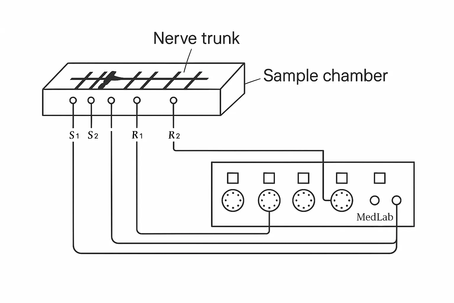
When collecting ECG from the body surface, two considerations are electrode placement and connection to the amplifier. Standardized electrode positions and amplifier connections are defined for consistent and comparable ECG waveforms, known as the lead system. The internationally accepted 12-lead standard includes leads I, II, III, aVR, aVL, aVF, and V1–V6. Leads I, II, and III are bipolar limb leads; the others are unipolar. Limb leads I, II, and III measure potential differences between right arm, left arm, and left leg pairs. Unipolar leads use a reference electrode and a probing electrode to reflect local cardiac potentials. Chest leads V1–V6 use a common reference electrode and probing electrodes placed at six chest positions. Leads aVR, aVL, and aVF are augmented limb leads that increase signal amplitude by altering the reference electrode.
3.3 First-stage amplification
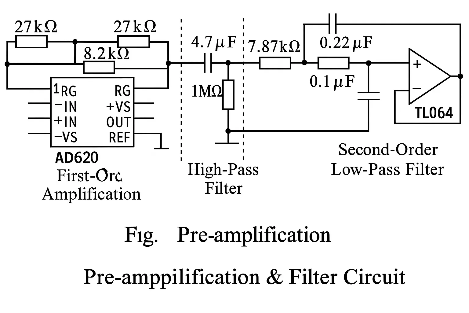
The first-stage amplifier uses the AD620 because of its high input impedance, high CMRR, and low noise and drift. The AD620 is a differential amplifier that effectively suppresses noise. The first-stage gain should not be excessive because electrode potential fluctuations, polarization voltages, and other noise could complicate downstream processing. A gain between 7 and 10 is recommended. The circuit connection is shown in Figure 2. The AD620 REF pin is tied to ground.
3.4 Filtering
Because ECG frequencies lie between 0.05 Hz and 100 Hz, the acquisition circuit must filter out frequencies outside this range. The filter stage comprises high-pass, low-pass, and a 50 Hz notch filter. A simple CR passive high-pass filter (Figure 2) blocks DC and reduces baseline drift, which is primarily caused by respiration. For sharper attenuation above the cutoff, a second-order low-pass filter was designed, as shown in Figure 2.
Practical measurements and calculations produced the results summarized in Table 1. In Table 1, attenuation values are measured data, while "Filterlab" denotes software simulation results. The measured and simulated data are generally consistent.
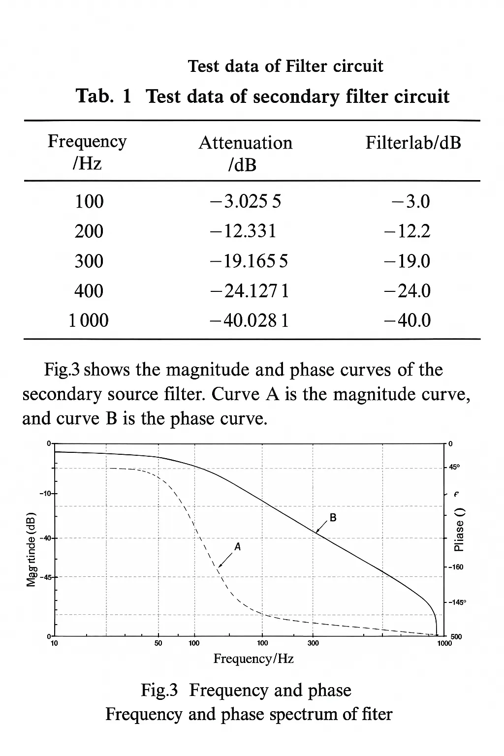
Figure 3 shows the amplitude-frequency and phase-frequency curves of the two-stage active filter. Curve A is the amplitude-frequency response and curve B is the phase-frequency response.
3.5 Notch filter
To suppress mains interference, a 50 Hz notch filter was designed using a twin-T band-stop topology. Implementing an effective notch requires careful selection and tuning of component values, and the use of high-precision resistors and capacitors to ensure strict matching. During experiments, five parameter sets were simulated and tested; although calculations indicated a 50 Hz cutoff for each set, many produced unsatisfactory real-world results. The final design and parameters are shown in Figure 4. Simulation of signals below 46 Hz passing through the notch circuit showed good agreement between the input signal A and the output signal B, with no distortion for signals below 46 Hz.
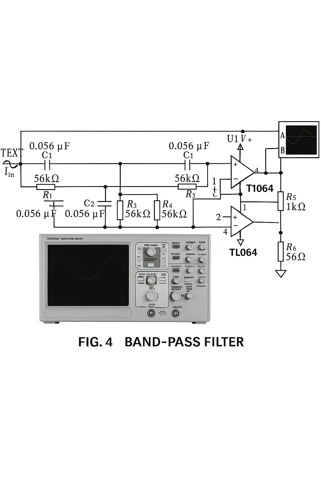
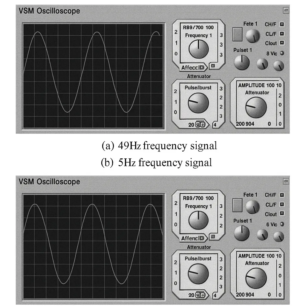
Figure 5 compares the input and output waveforms for 49 Hz and 50 Hz signals passing through the notch filter. The results show that a 49 Hz input is attenuated to about 0.35 times the original amplitude. For a 50 Hz input, the signal is almost completely attenuated, indicating effective suppression of 50 Hz mains interference.
3.6 Main amplifier
To meet the A/D converter input range, the two-stage amplification provides approximately 1000× total gain. With the first stage set to 8×, the second stage is designed for 125×. For integration and cost considerations, the TL064 was selected. The TL064 integrates four operational amplifiers, each with a power consumption of about 6 mW, which suits portable products. The amplifier stage uses a simple feedback topology with adjustable resistor values for gain control.
4 Digital processing
4.1 A/D conversion
The amplified analog signals must be digitized for storage and display. Sampling rate and converter selection are primary concerns.
The American Heart Association recommends a sampling rate of 500 Hz, but practical applications use various rates between 125 Hz and 1000 Hz. Monitoring commonly uses 200 Hz or 250 Hz, analysis may use 400–500 Hz, and Holter recordings typically use 125–200 Hz. Resolution is typically 10-bit or 12-bit.
Converter selection depends on architecture, conversion rate, channel count, resolution, power consumption, and supply voltage. Table 2 lists candidate A/D converters for comparison.
Based on Table 2 and project requirements, the MAX197 was selected for its suitable resolution, conversion rate, power consumption, and size. It provides eight analog inputs, allowing acquisition of up to eight channels, matching multi-lead ECG requirements.
Control logic was implemented in VHDL. According to the MAX197 timing diagram, a finite-state machine approach realizes the control module. The conversion process is divided into five states: 1) initialization, writing control words for read/write, channel selection, and voltage range; 2) start conversion, where a clock-driven signal initiates conversion; 3) check conversion completion, looping until conversion finishes; 4) read the lower 8 bits by asserting the low-byte enable signal; 5) read the upper 4 bits by asserting the high-byte enable signal.
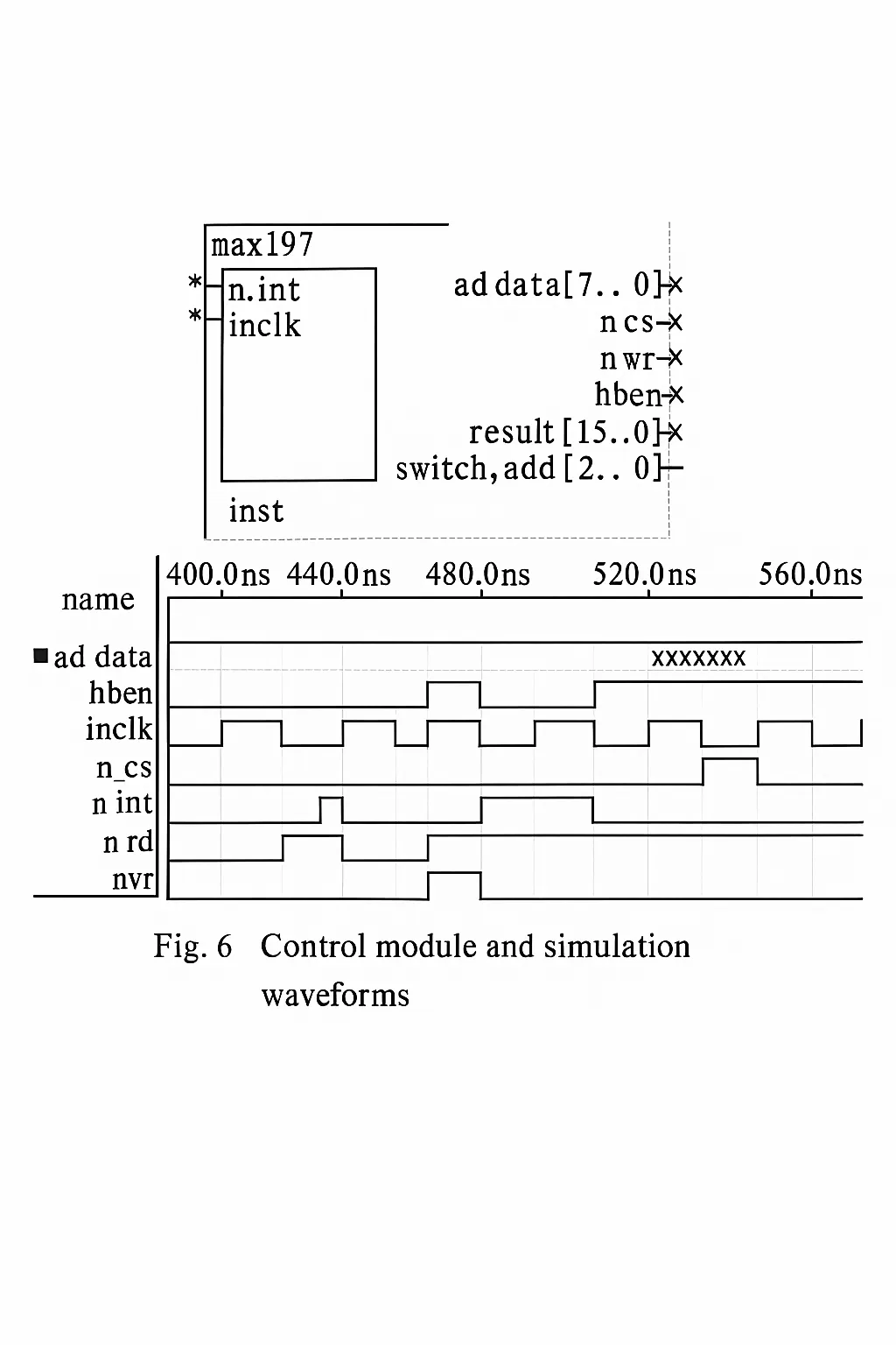
Figure 6 shows the generated symbol and simulation waveforms after implementing the state machine in VHDL. The simulation indicates the module meets the converter timing requirements and provides the required digital output.
The FPGA supplies the A/D converter control signals. An FPGA was chosen as the control platform because it provides abundant programmable logic resources to implement control, storage, display, keys, communication, and other modules on a single chip. Integrating these modules in the FPGA reduces device size and improves reliability, aligning with the overall project architecture.
5 Conclusion
Based on project requirements and ECG signal characteristics, an acquisition circuit was designed with targeted considerations for amplitude, frequency, and noise. Each stage was simulated and tested, and the circuit was minimized to meet the size constraints of a portable device while maintaining high performance for effective ECG acquisition. The amplified signals are digitized under FPGA control for subsequent digital processing. Given the FPGA's programmable resources, the acquisition system can be expanded into a diagnostic and display system.