 ALLPCB


Metal core printed circuit boards provide a practical approach to thermal management in high-power electronic assemblies. These boards incorporate a metal substrate, typically aluminum or copper, that conducts heat away from components more effectively than standard fiberglass materials. Engineers often evaluate metal core PCB cost against long-term reliability gains, especially in applications such as LED lighting, power converters, and automotive electronics. The initial material and processing expenses can appear higher, yet reduced cooling hardware and extended product life frequently offset those costs. Proper design choices further influence overall thermal PCB cost and system economics.
What Are Metal Core PCBs and Why Thermal Management Matters
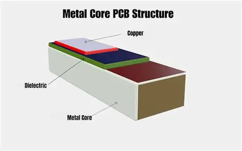
A metal core PCB consists of a metal base layer, a thin dielectric insulator, and a copper circuit layer. The metal substrate serves as both mechanical support and primary heat path. This construction differs from conventional FR4 boards, where heat dissipates slowly through the epoxy-glass composite. In power-dense designs, inadequate thermal management leads to elevated junction temperatures, accelerated component aging, and potential field failures. Industry standards such as IPC-6012E define performance requirements for rigid boards, including those with metal cores, ensuring consistent quality across production lots.
Thermal management directly affects total ownership cost. Effective heat spreading allows designers to maintain safe operating temperatures without oversized heatsinks or forced-air systems. Consequently, aluminum PCB cost considerations extend beyond the bare board to include assembly, enclosure, and warranty expenses. Procurement teams routinely compare metal core PCB cost with alternative cooling strategies during the concept phase. When thermal demands are moderate, selective use of metal cores in critical sections can optimize spending while meeting reliability targets.
Thermal Management Mechanisms in Metal Core PCBs
Heat conduction through the metal core follows Fourier’s law, where thermal conductivity of the substrate material governs the rate of temperature equalization. Aluminum offers a favorable balance of conductivity, weight, and expense, while copper provides higher performance at increased material cost. The dielectric layer between the copper traces and the metal base must balance electrical insulation with thermal transfer; thinner dielectrics improve heat flow but raise manufacturing complexity and potential defect rates.
Component placement and trace layout further modulate thermal resistance. Concentrating high-dissipation devices near the board center or along high-conductivity paths minimizes hot spots. Finite-element thermal modeling helps quantify these effects before fabrication, reducing the need for costly prototype iterations. Standards such as IPC-A-600K provide acceptance criteria for finished boards, covering aspects that influence long-term thermal performance, including dielectric integrity and copper adhesion.
Warpage control becomes critical during reflow because mismatched coefficients of thermal expansion between layers can distort the assembly. Manufacturers apply controlled lamination pressures and cure profiles to maintain flatness within tolerances suitable for surface-mount processes. These process controls contribute to overall metal core PCB cost yet prevent downstream assembly defects that would otherwise increase total project expense.
Cost Factors and Practical Solutions for Thermal Management
Material selection represents the largest variable in MCPCB cost. Aluminum substrates generally cost less than copper while delivering adequate conductivity for many applications. Dielectric thickness, thermal conductivity rating, and copper weight all influence pricing and performance. Thicker copper layers improve current-carrying capacity and heat spreading but add expense and etching time.
Design optimization offers the most direct path to cost reduction. Engineers can limit metal core usage to high-power zones while retaining standard materials elsewhere, creating hybrid constructions that control thermal PCB cost. Component derating, strategic via placement for heat transfer, and selection of thermally enhanced packages further lower required cooling provisions. These measures reduce the size or eliminate external heatsinks, yielding measurable savings in mechanical hardware and assembly labor.
Process considerations during manufacturing also affect economics. Panel utilization, yield rates, and secondary operations such as surface finishing or mechanical machining influence final board price. Early collaboration between design and fabrication teams helps align layout features with standard production capabilities, avoiding premium charges for non-standard tolerances. Consistent application of IPC-6012E requirements supports predictable yields and repeatable thermal performance across production runs.

Conclusion
Metal core PCBs deliver measurable thermal advantages that translate into system-level cost benefits when thermal demands are properly quantified. Material choices, dielectric properties, and layout strategies determine both upfront metal core PCB cost and downstream reliability expenses. Adherence to established standards such as IPC-6012E and IPC-A-600K supports consistent quality and predictable performance. Thoughtful integration of these boards into power electronics designs often reduces or eliminates auxiliary cooling components, improving overall product economics without compromising safety margins.
FAQs
Q1: What factors most influence metal core PCB cost?
A1: Material selection, dielectric thickness, copper weight, and panel utilization drive the majority of pricing differences. Design complexity and required thermal conductivity ratings also affect fabrication steps and yield. Early involvement of manufacturing expertise helps identify cost-effective configurations that still meet thermal targets.
Q2: How does aluminum PCB cost compare with traditional FR4 boards for thermal applications?
A2: Aluminum-based boards typically carry a higher per-unit price than standard FR4, yet they often reduce total system cost by minimizing heatsink size, fan requirements, and warranty claims related to overheating. The net economic benefit depends on power density and operating environment.
Q3: What role does thermal management play in overall PCB thermal management cost?
A3: Effective heat spreading through the metal core lowers the need for external cooling hardware and allows tighter component packing. This integration frequently offsets the incremental board expense through simplified mechanical design and improved reliability.
Q4: Are there industry standards that guide metal core PCB quality and performance?
A4: IPC-6012E and IPC-A-600K establish qualification and acceptability criteria applicable to metal core constructions. These documents help ensure consistent electrical, mechanical, and thermal characteristics across suppliers and production lots.
References
IPC-6012E — Qualification and Performance Specification for Rigid Printed Boards. IPC, 2017
IPC-A-600K — Acceptability of Printed Boards. IPC, 2020
ISO 9001:2015 — Quality Management Systems. ISO, 2015


