 ALLPCB


Introduction
In the fast-paced world of PCB prototyping, engineers often face the challenge of balancing precision with budget constraints. Manual stencil printers emerge as a practical choice for low-volume production, enabling accurate solder paste application without the high costs of automated systems. These tools are particularly valuable for electric engineers working on custom designs or iterative prototypes where small batch sizes dominate. By facilitating controlled deposition of solder paste, manual stencil printers streamline the surface-mount technology (SMT) assembly process. This approach minimizes defects and accelerates time-to-test, making it ideal for in-house operations. As demands for rapid prototyping grow, understanding manual stencil printers becomes essential for efficient workflow.
What Are Manual Stencil Printers and Why They Matter for Low-Volume Prototyping
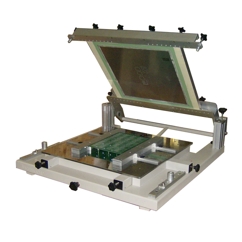
Manual stencil printers are benchtop devices designed for applying solder paste through a stencil onto PCB pads using a squeegee blade. Unlike automated printers, they rely on operator control for alignment, pressure, and speed, which suits low-volume runs effectively. For electric engineers prototyping circuits with fine-pitch components, these printers offer repeatability without requiring extensive setup or maintenance. Their cost-effectiveness stems from simple mechanical designs, often featuring adjustable frames and fixtures that accommodate various board sizes. In high-volume scenarios, automation excels, but for prototypes under 100 units, manual options reduce overhead while maintaining quality. This relevance intensifies in R&D environments where frequent design changes demand flexibility.
The importance lies in enabling DIY stencil printer approaches, where engineers can achieve professional-grade paste deposition at a fraction of outsourcing costs. Poor paste application leads to issues like bridging or insufficient volume, compromising reflow soldering outcomes. Manual printers address this by providing tactile feedback, allowing real-time adjustments. They align with lean manufacturing principles, conserving resources for small-scale electric engineers. Ultimately, these tools bridge the gap between hand-soldering and full production, fostering innovation in PCB assembly.
Technical Principles of Manual Stencil Printing
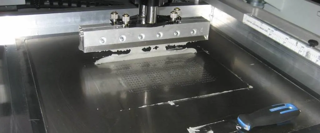
Stencil printing operates on the principle of controlled paste transfer through laser-cut apertures in a thin metal foil, typically stainless steel. The process begins with precise registration of the stencil over the PCB, ensuring apertures align with pads to within tight tolerances. A squeegee then sweeps across the stencil, exerting downward pressure to force paste into the openings while shearing excess material. This shear-thinning behavior of solder paste, a non-Newtonian fluid, ensures clean release from the stencil walls upon lift-off. Key parameters include squeegee angle, typically 45 to 60 degrees, speed, and pressure, which influence paste volume and uniformity.
Adherence to IPC-7525B guidelines for stencil design optimizes these mechanics, recommending aperture reductions of 5 to 10 percent relative to pad size for fine-pitch features. Proper stencil tension prevents warping, maintaining flatness critical for micron-level accuracy. Paste rheology plays a role too, with type 4 or 5 pastes preferred for small apertures to avoid clogging. Engineers must consider board warpage and stencil thickness, often 0.1 to 0.15 mm, to match component pitches. These principles ensure consistent gasketing, where the stencil seals against the PCB, preventing paste bleed.
Features of the Best Manual Stencil Printer
When evaluating the best manual stencil printer, prioritize robust construction with a stable base to minimize vibration during operation. Adjustable fixturing systems, such as pin registration or vacuum hold-downs, enhance alignment repeatability, crucial for multi-panel prototypes. Look for stencil frames that accommodate standard sizes while allowing quick swaps, reducing downtime in iterative workflows. Squeegee mechanisms with variable pressure controls and dual-blade options support both directions, improving paste distribution uniformity.
In a manual stencil printer review, ease of cleaning stands out, as residue buildup affects print quality over sessions. Features like hinged stencil clamps and accessible wipe stations facilitate maintenance per IPC-7526A recommendations for understencil cleanliness. Portability matters for lab environments, with compact footprints under 1 square meter ideal. Durability in metal components resists wear from abrasive pastes, extending service life. For DIY stencil printer enthusiasts, modular designs permit custom adaptations, such as height-adjustable platforms for warped boards.
Superior models incorporate visual aids like fiducial alignment marks or transparent stencils for verification. Snap-in PCB nests speed setup for low-volume runs, while angle-adjustable squeegees optimize shear force. These attributes collectively define the best manual stencil printer, balancing precision, usability, and affordability for electric engineers.
Best Practices for Optimal Results
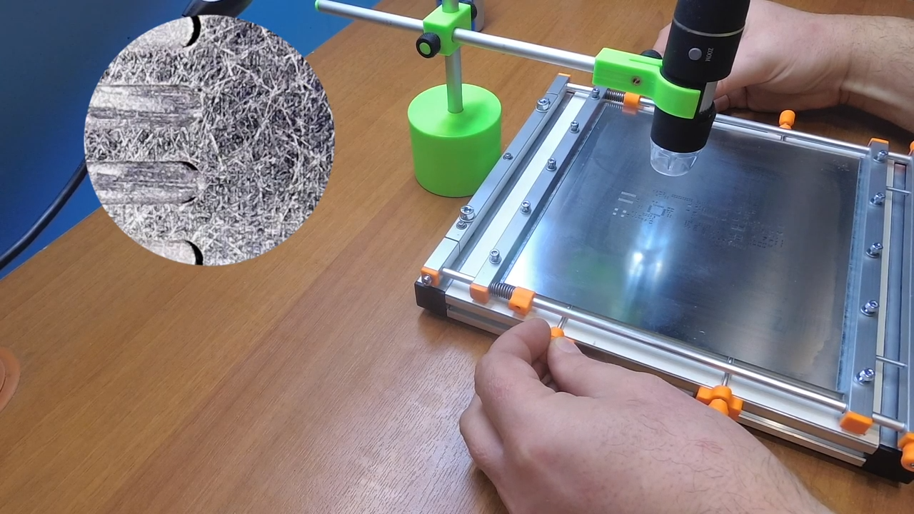
Start with thorough preparation: clean the PCB and stencil to remove particulates, using isopropyl alcohol and lint-free wipes. Align fiducials under magnification, securing the assembly with clamps to prevent shift. Apply paste sparingly to the stencil, using a spatula for even loading without air pockets. Sweep the squeegee in one direction at consistent speed, around 20 to 50 mm per second, with moderate pressure to achieve 100 percent transfer efficiency.
Post-print inspection via automated optical systems or manual gauging verifies volume and placement. J-STD-001 requirements guide acceptability, emphasizing uniform deposits free of voids or bridges. Clean the stencil immediately after each print, employing automated wipe sequences if available. Store paste in refrigerated conditions and remix before use to maintain viscosity. For low-volume prototyping, batch prints on panels to maximize efficiency.
Document process parameters in a log for traceability, adjusting based on reflow feedback. Use type 3 or finer pastes for prototypes with 0.4 mm pitch components. Practice on scrap boards refines technique, reducing scrap rates. These practices ensure reliable SMT assembly outcomes.
Troubleshooting Common Issues in Manual Stencil Printing
Insufficient paste volume often traces to inadequate squeegee pressure or high stencil lift speed; increase pressure incrementally and slow the motion. Bridging between pads signals excessive paste or poor aperture design; refine stencil per IPC-7525B by adding home plating or reducing aperture width. Smearing results from dirty stencils or improper gasketing; enhance cleanliness and verify flatness with a straightedge.
Stencil clogging demands immediate attention: pause printing, wipe underside, and inspect apertures under light. Warped PCBs cause uneven deposits; employ adjustable supports or bake boards to relieve stress. Inconsistent prints across panels indicate frame tension loss; retension or replace foil. For DIY stencil printer setups, makeshift jigs may introduce misalignment; invest in precision fixtures.
Paste drying leads to poor release; limit open time and use humidity-controlled environments. Systematic troubleshooting, coupled with standard adherence, resolves most issues swiftly.
Conclusion
Manual stencil printers deliver a cost-effective pathway for low-volume PCB prototyping, empowering electric engineers with precise, repeatable paste application. By mastering alignment, pressure control, and maintenance, users achieve production-like quality in-house. Standards like IPC-7525B and J-STD-001 provide foundational guidance, ensuring reliability. Whether opting for the best manual stencil printer or a DIY stencil printer variant, these tools accelerate innovation while curbing expenses. Integrate best practices to troubleshoot effectively, elevating prototype success rates. For sustained efficiency, prioritize features that match your workflow demands.
FAQs
Q1: What makes the best manual stencil printer for low-volume PCB work?
A1: The best manual stencil printer features sturdy fixturing, adjustable squeegee pressure, and easy-clean designs for repeatability. Prioritize models with pin registration for precise alignment on prototypes. These attributes minimize defects like bridging, supporting fine-pitch components effectively. Compact size suits lab benches, while durable builds handle daily use. Overall, focus on usability and stability for optimal results.
Q2: How does a manual stencil printer review highlight DIY advantages?
A2: In a manual stencil printer review, DIY stencil printer setups shine for cost savings and customizability in prototyping. Simple jigs with magnetic holds or V-slot systems enable accurate paste application without automation costs. Troubleshooting focuses on alignment tweaks for consistent volumes. They excel for small batches, reducing outsourcing waits. Engineers gain hands-on control, refining processes iteratively.
Q3: What are key best practices for using a manual stencil printer?
A3: Align fiducials precisely, apply moderate squeegee pressure, and clean after each print to ensure uniform paste. Use finer pastes for small apertures and inspect deposits immediately. Adhere to cleanliness per industry guidelines to prevent clogging. Log parameters for repeatability in low-volume runs. These steps yield reliable SMT prototypes with minimal rework.
Q4: Can manual stencil printers handle fine-pitch components in prototypes?
A4: Yes, manual stencil printers manage fine-pitch effectively with proper stencil design and technique. Thinner foils and reduced apertures prevent excess paste, aligning with SMT standards. Controlled sweeps avoid bridging on 0.4 mm pitches. Practice and fixturing enhance precision for electric engineers. They prove viable for prototypes before scaling.
References
IPC-7525B — Stencil Design Guidelines. IPC, 2011
IPC-7526A — Stencil and Misprinted Board Cleaning Handbook. IPC, 2007
J-STD-001 — Requirements for Soldered Electrical and Electronic Assemblies. IPC, 2017


