ALLPCB


Introduction
Developing embedded vision systems does not require expensive FPGAs or SoCs, large frame buffer memory, and external cameras. A cost-optimized FPGA/SoC that connects directly to a CMOS image sensor can implement powerful image-processing systems while meeting size, cost, and power targets.
Direct sensor interfacing is similar to a camera interface: unlike receiving video via HDMI or CameraLink, connecting to an image sensor typically delivers data in parallel formats (for example, MI PI or raw parallel). Before receiving video, the imager must be configured to operate as required. Configuration is commonly performed over I2C or SPI, and the number of commands sent by the host can be large.
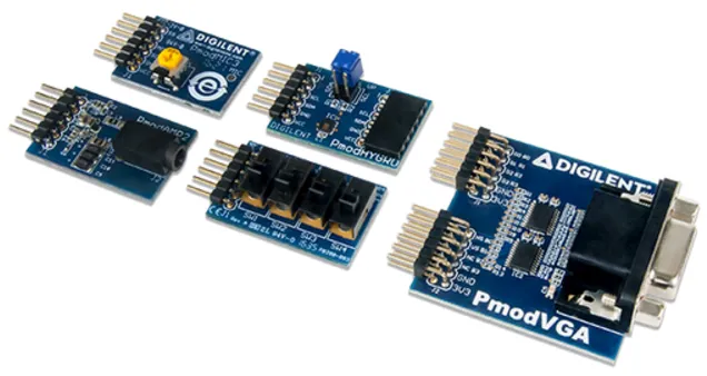
To demonstrate integration of a sensor with a cost-optimized FPGA, this article examines integration of the TDNext 1.26-megapixel Pmod. The example targets an Arty S7-50. Because the Arty S7 does not provide HDMI or other video output on-board, this example uses an Avnet 10-inch touchscreen, although the Digilent Pmod VGA is an alternative for final image output and can enable a lower-cost solution.
The TDNext Pmod interface is divided into two elements: video and configuration. The video interface consists of 10-bit pixels (an 8-bit MSB bus plus 2 LSBs), frame and line valid signals, a pixel clock, and a 24 MHz reference clock. The configuration interface consists of I2C connected to the imager and an I2C IO expander used to generate a reset to the imager.
The architecture used here configures the imager via a soft-core processor over I2C. The image-processing path is implemented entirely inside the FPGA. Since this is a low-cost application, no external DDR frame buffer is used; the image-processing pipeline operates fully within the FPGA fabric. The soft-core processor also manages video timing and other configuration tasks for the image-processing path.
Background
TDNext is a color imager that applies a Bayer pattern so each pixel senses photons of a single color (red, green, or blue) during integration. When integration completes, pixels are read out as 8-bit or 10-bit values, commonly referred to as RAW8 or RAW10. A demosaic algorithm reconstructs a full-color image by combining neighboring pixel values that correspond to different wavelengths.
Vivado Build
The first step is to create a Vivado platform that accepts image data from the TDNext Pmod. The block design primarily uses IP cores from the Vivado library plus a camera-interface block and Avnet display output IP.
Install the board definition files so Vivado recognizes the Arty S7. After download, place the files under:
<install_path>/Vivado/<version>/data/boards/board_files/
This allows selecting the Arty S7 board as the target when creating a new Vivado project. After installing the board files, create a new project, build the block diagram, and instantiate a MicroBlaze system.
With MicroBlaze running, add the video-processing pipeline. The processing chain in this design uses the following IP blocks:
- Camera interface - interfaces to the TDNext video signals
- Video to AXIS - converts parallel video to AXI-Stream format
- Sensor demosaic - converts RAW R/G/B pixel values into 24-bit RGB
- Video Timing Generator (VTC) - generates output video timing signals
- AXI Stream to Video Out - converts AXI-Stream back to parallel video
- ZedALI3 controller - drives the 10-inch touchscreen (omit if using Pmod VGA)
- AXI IIC - connects to MicroBlaze and is used to configure the imager
- AXI UART - connects to MicroBlaze for status reporting
Before adding ZedALI3 and the camera interface, repackage the required IP to support the Spartan-7 device. From the IP catalog, select the IP, choose "Edit IP" in the packager, add Spartan-7 support on the compatibility tab, repackage the IP, and update the project IP repository. Once the IP is upgraded for Spartan-7, complete the design.
Unlike previous heterogeneous SoC examples that used an external frame buffer, this design omits VDMA to/from external memory. Typically AXI Stream to Video is configured as master and VTC as unmanaged; in this approach AXI Stream to Video is configured as a slave and the VTC generator clock enable is controlled. This lets the AXI Stream to Video IP control sync timing by enabling and disabling the VTC so it matches the processing pipeline timing.
Within AXI-Stream, the start of frame is indicated by TUSER and end-of-line by TLAST. Key IP customization includes:
- Video input to AXI4-Stream configuration
- Sensor demosaic settings
- AXI IIC configuration
Several Integrated Logic Analyzers (ILAs) were added to monitor internal signals and assist debugging. After implementation, the overall utilization on Arty S7-50 is shown in the project report. There are additional resources available for implementing image-processing algorithms using HLS if required. To reduce resource use, a minimal MicroBlaze configuration and removal of ILAs are possible.
Writing Software in the SDK
After generating the Vivado hardware, the next step is to write the application software that configures the imager and the IP cores in the video-processing path. The software performs the following tasks:
- Initialize AXI IIC, VTC, and interrupt controller
- Set up interrupt handlers for AXI IIC send, receive, and status interrupts
- Configure timing on the VTC for the 10-inch display
- Reset the camera via I2C and toggle the PMOD LEDs
- Detect the camera over I2C (the application looks for an MT9M114)
- Download multiple I2C configuration settings to initialize the camera (this takes several seconds)
To initialize the imager, the Zynq-based TDM114 example library was adapted for use with AXI IIC. After camera initialization, video frames can be observed on the ILA connected to the AXI-Stream components.
Monitoring I2C traffic on the TDNext Pmod shows communication between the Arty S7 and the TDNext. Once the camera is detected, the application uploads multiple I2C configuration registers. Progress is reported via AXI UART.
With the camera initialized, the ILA can verify that the sensor is producing video at the configured resolution. The received pixels are converted from parallel format to AXI-Stream. AXI-Stream is a unidirectional bus for data flow without an address channel. The following signals control flow and convey timing information across AXI-Stream:
- TREADY - asserted by the downstream element when ready to receive data
- TVALID - asserted by the sender when output data is valid
- TUSER - indicates the start of a frame
- TLAST - indicates the end of a line
A second ILA ensures the AXI-Stream is correctly formed. Because no VDMA is used, it is important that the video on the AXI-Stream is a contiguous block and that TVALID remains asserted during active pixels. Using the pixel clock through the image-processing chain ensures TVALID remains continuous.
The project uses standard Xilinx library headers plus a camera_initial.h file containing I2C configuration data. The device addresses and identifiers are defined in those headers. The main application loop structure used in the example is shown below.
int main()
{
    u32 Status;
    XIic_Config *iic_conf;
    XVtc VtcInst;
    XVtc_Config *vtc_config;
    XVtc_Timing vtcTiming;
    XVtc_SourceSelect SourceSelect;
    XV_demosai_Config *mosaic_config;
    init_platform();
    printf("www. adi uvoengineering.com S7 Imager example ");
    mosaic_config = XV_demosaic_LookupConfig(XPAR_XV_DEMOSAIC_0_DEVICE_ID);
    XV_demosaic_CfgInitialize(&mosaic,mosaic_config,mosaic_config->BaseAddress);
    XIntc_Initialize(&InterruptController, int_dev);
    SetUpInterruptSystem();
    iic_conf = XIic_LookupConfig(IIC_dev);
    Status = XIic_CfgInitialize(&iic, iic_conf, iic_conf->BaseAddress);
    if (Status != XST_SUCCESS) {
        printf("XIic initial is fail ");
        return XST_FAILURE;
    }
    XIic_SetSendHandler(&iic, &iic, (XIic_Handler) SendHandler);
    XIic_SetRecvHandler(&iic, &iic, (XIic_Handler) ReceiveHandler);
    XIic_SetStatusHandler(&iic, &iic,(XIic_StatusHandler) StatusHandler);
    vtc_config = XVtc_LookupConfig(XPAR_VTC_0_DEVICE_ID);
    XVtc_CfgInitialize(&VtcInst, vtc_config, vtc_config->BaseAddress);
    vtcTiming.HActiveVideo = 1280;
    vtcTiming.HFrontPorch = 65;
    vtcTiming.HSyncWidth = 55;
    vtcTiming.HBackPorch = 40;
    vtcTiming.HSyncPolarity = 0;
    vtcTiming.VActiveVideo = 800;
    vtcTiming.V0FrontPorch = 7;//8;
    vtcTiming.V0SyncWidth = 4;
    vtcTiming.V0BackPorch = 12;
    vtcTiming.V1FrontPorch = 7;
    vtcTiming.V1SyncWidth = 4;
    vtcTiming.V1BackPorch = 12;
    vtcTiming.VSyncPolarity = 0;
    vtcTiming.Interlaced = 0;
    memset((void *)&SourceSelect, 0, sizeof(SourceSelect));
    SourceSelect.VBlankPolSrc = 1;
    SourceSelect.VSyncPolSrc = 1;
    SourceSelect.HBlankPolSrc = 1;
    SourceSelect.HSyncPolSrc = 1;
    SourceSelect.ActiveVideoPolSrc = 1;
    SourceSelect.ActiveChromaPolSrc= 1;
    SourceSelect.VChromaSrc = 1;
    SourceSelect.VActiveSrc = 1;
    SourceSelect.VBackPorchSrc = 1;
    SourceSelect.VSyncSrc = 1;
    SourceSelect.VFrontPorchSrc = 1;
    SourceSelect.VTotalSrc = 1;
    SourceSelect.HActiveSrc = 1;
    SourceSelect.HBackPorchSrc = 1;
    SourceSelect.HSyncSrc = 1;
    SourceSelect.HFrontPorchSrc = 1;
    SourceSelect.HTotalSrc = 1;
    XVtc_RegUpdateEnable(&VtcInst);
    XVtc_SetGeneratorTiming(&VtcInst,&vtcTiming);
    XVtc_SetSource(&VtcInst, &SourceSelect);
    XVtc_EnableGenerator(&VtcInst);
    XIic_Reset(&iic);
    PCA9534_CTRL ();
    Detect_Camera();
    Soft_Reset_Camera();
    Initial_Camera();
    XV_demosaic_Set_HwReg_width(&mosaic,0x500);
    XV_demosaic_Set_HwReg_height(&mosaic,0x31f);
    XV_demosaic_Set_HwReg_bayer_phase(&mosaic,0x1);
    XV_demosaic_EnableAutoRestart(&mosaic);
    XV_demosaic_Start(&mosaic);
    while(1){
    }
    cleanup_platform();
    return 0;
}
Some settings were adjusted to increase integration time, but the basic image-processing pipeline operates as expected.
Conclusion
It is straightforward to create a vision-processing system that interfaces directly to an imager rather than a camera module. Reducing the processing chain typically enables a lower-cost solution with potential latency benefits.