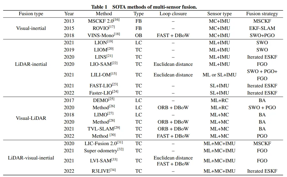
ALLPCB


Overview
With the expansion of new-energy vehicles and increased vehicle intelligence, automotive cameras have become widely used. As a key sensor for driver assistance and autonomous functions, camera performance and safety are critical. During electrostatic discharge (ESD) testing, common faults such as image corruption and device lockup challenge system stability and can create safety risks. This article examines root causes of automotive camera ESD issues and practical mitigation strategies.
1. Basic camera structure
An automotive camera typically consists of three main parts: the front cover (lens), the rear cover or connector region, and the internal electronics (circuit board). The internal circuit is the core component, and circuit designs vary by interface and protocol. Although the mechanical structure is relatively simple, circuit layout and design are key factors for addressing ESD performance.
2. ESD symptoms
Two common failure modes observed during ESD testing are:
- Image corruption: symptoms include flicker, visual noise, or “snow” in the video output.
- Device lockup or blackout: the video freezes or the camera becomes unresponsive, possibly going to black screen.
Both conditions degrade functionality and can pose risks when cameras are used for driver assistance or safety-critical features.
3. Mitigation strategies
ESD robustness can be improved through a combination of mechanical, grounding, and material choices:
- Enclosure selection: A metal housing provides shielding benefits and can improve electromagnetic compatibility (EMC) as well as ESD immunity. However, using metal requires careful attention to grounding to ensure sufficiently low impedance and multiple grounding points where appropriate.
- Grounding methods: Some modules rely on PCB features such as dedicated plated screw holes or “copper relief” areas for chassis grounding. If fasteners or plating degrade conductivity, grounding effectiveness is compromised. Use conductive fasteners and verify low-resistance contact. Additional options include PCB edge copper, metal spring contacts, or metal shielding cans to achieve reliable chassis ground.
- Adhesive or potting considerations: Applying adhesive or potting between the PCB and housing can increase insulation and reduce the frequency of ESD events by preventing direct contact. However, potting can impair heat dissipation and will not eliminate ESD effects caused by capacitive or radiative coupling to sensitive ICs. Evaluate thermal impact and residual coupling paths when using potting or gasketing.
4. Recommendations
To improve ESD robustness in automotive camera modules, prioritize a comprehensive approach:
- Adopt a shielding-capable enclosure (often metal) and implement low-impedance, multi-point grounding between the PCB and chassis.
- Specify conductive fasteners and verify long-term contact reliability at grounding interfaces.
- Seal lens-housing interfaces to reduce charge ingress while maintaining optical and mechanical integrity.
- Balance ESD measures with other requirements such as thermal management and EMC by validating through targeted testing and iterative design adjustments.
Through proper structural design, reliable grounding practices, and careful material selection, ESD susceptibility can be significantly reduced, improving the stability and reliability of automotive camera systems used in driver assistance and autonomous applications.