 ALLPCB


In the world of printed circuit board (PCB) design, the ground plane is a critical element that ensures stability, performance, and reliability. For metal core PCBs (MCPCBs), which are often used in high-power and high-heat applications, the ground plane takes on even greater importance. This blog post dives deep into the design principles of ground planes in PCBs, with a focus on metal core PCBs. We’ll explore key aspects such as guided ground planes, noise reduction, heat dissipation, and EMI/RFI shielding capabilities to help engineers and designers optimize their projects.
Whether you’re designing for LED lighting, automotive systems, or power electronics, understanding how to implement an effective ground plane can make a significant difference. Let’s break down these principles step by step to provide actionable insights for your next PCB design.
What Is a Ground Plane in PCB Design?
A ground plane in a PCB is a large area of conductive material, usually copper, that serves as a common reference point for electrical signals. It acts as a return path for currents, reduces noise, and helps maintain signal integrity. In metal core PCBs, the ground plane often works alongside a metal substrate (typically aluminum or copper) to enhance thermal management and structural stability.
The primary functions of a ground plane include providing a low-impedance path for return currents, minimizing electromagnetic interference (EMI), and aiding in heat dissipation. For MCPCBs, which are designed to handle high power and heat, the ground plane’s role becomes even more critical. Let’s explore how to design it effectively.
Key Design Principles of Ground Planes in Metal Core PCBs
Designing a ground plane for a metal core PCB requires careful consideration of several factors. Below, we’ll cover the core principles, focusing on guided ground planes, noise reduction, heat dissipation, and EMI/RFI shielding capabilities.
1. Understanding Guided Ground Planes in PCB Design
Guided ground planes refer to a structured approach where the ground plane is designed to control the path of return currents and minimize interference. This is especially important in high-speed and high-frequency applications where signal integrity is paramount.
In a metal core PCB, the ground plane must be positioned to guide return currents directly beneath signal traces to reduce loop inductance. A typical loop inductance for a poorly designed ground plane might be in the range of 10-20 nH, leading to signal delays and noise. By contrast, a well-guided ground plane can reduce this to under 5 nH, improving performance significantly.
Tip for Implementation: Ensure that the ground plane is continuous and unbroken beneath critical signal traces. Avoid splitting the ground plane unless absolutely necessary, as splits can force return currents to take longer paths, increasing noise and EMI risks.
2. Noise Reduction with Ground Planes
Noise reduction is one of the primary reasons for using a ground plane in any PCB design. Electrical noise, such as crosstalk or ground bounce, can disrupt signal integrity and cause system failures. In metal core PCBs, where high currents are common, noise can be even more problematic.
A solid ground plane minimizes noise by providing a low-impedance path for return currents. For instance, in a high-speed digital circuit operating at 100 MHz, a poorly designed ground plane might result in noise levels of 50-100 mV, while a well-designed plane can reduce this to under 10 mV.
Best Practices for Noise Reduction:
- Keep the ground plane as close as possible to the signal layer to reduce parasitic inductance.
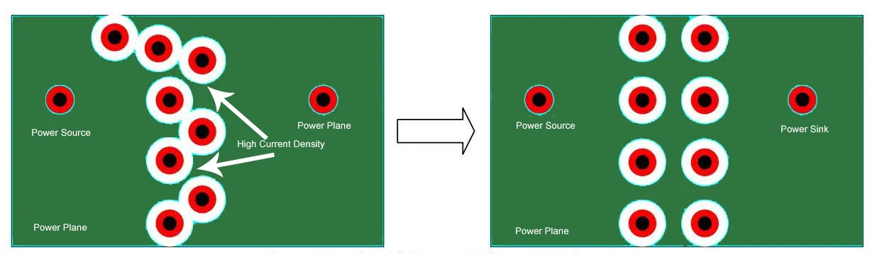
- Use multiple vias to connect components to the ground plane, ensuring a short return path.
- Avoid routing high-speed signals over gaps or splits in the ground plane.
In MCPCBs, noise reduction is further enhanced by the metal core, which can act as an additional grounding layer if designed properly. This dual grounding approach can significantly lower noise in power-intensive applications.
3. Heat Dissipation in Metal Core PCBs
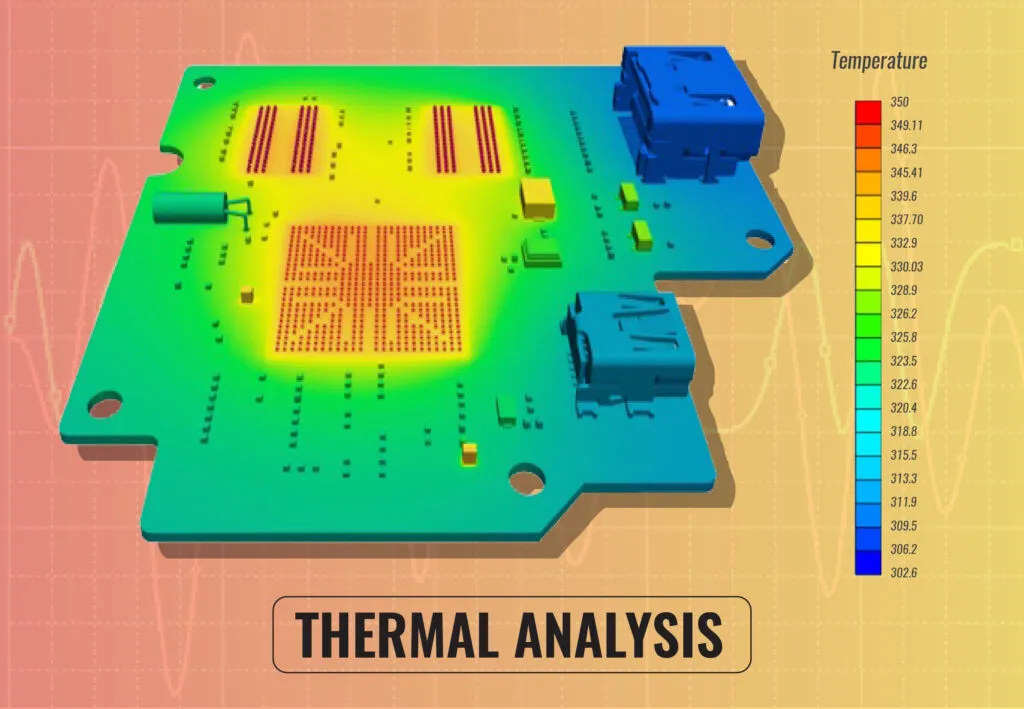
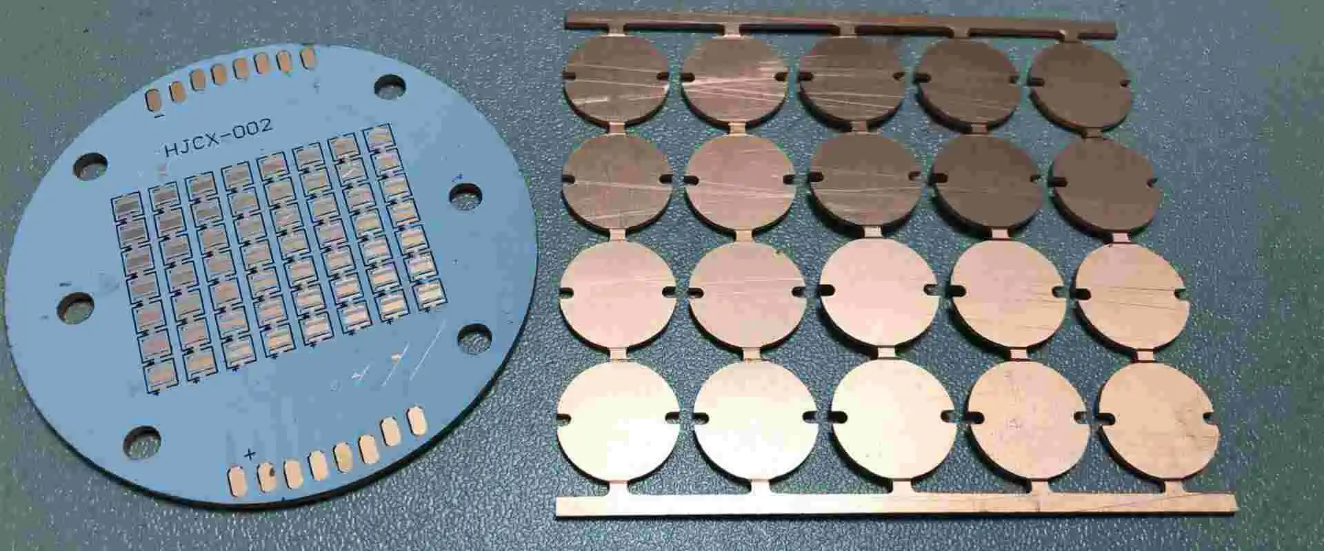
Heat dissipation is a standout feature of metal core PCBs, making them ideal for applications like LED lighting and power supplies. The metal core, often aluminum or copper, acts as a heat sink, drawing thermal energy away from components. The ground plane plays a complementary role by spreading heat across the board.
In a typical MCPCB design, the ground plane can be thermally connected to the metal core using vias or direct contact. This setup can reduce the thermal resistance of the board to as low as 1-2°C/W, compared to 5-10°C/W in standard FR4 PCBs. For high-power components dissipating 10W or more, this can mean the difference between overheating and reliable operation.
Design Tips for Heat Dissipation:
- Maximize the area of the ground plane to enhance heat spreading.
- Use thermal vias to connect the ground plane to the metal core for efficient heat transfer.
- Place high-power components near the ground plane to minimize thermal resistance.
By optimizing the ground plane for heat dissipation, designers can extend the lifespan of components and improve overall system reliability.
4. EMI/RFI Shielding Capabilities of Ground Planes
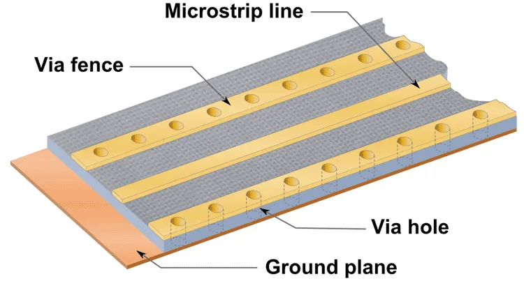
Electromagnetic interference (EMI) and radio frequency interference (RFI) are major concerns in PCB design, especially for applications in automotive, telecommunications, and industrial sectors. A well-designed ground plane acts as a shield, reducing the emission and susceptibility of EMI/RFI.
In metal core PCBs, the ground plane works alongside the metal core to create a robust barrier against interference. For example, in a high-frequency design operating at 2.4 GHz, a continuous ground plane can reduce EMI emissions by up to 20 dB compared to a fragmented or poorly designed plane.
Strategies for EMI/RFI Shielding:
- Ensure the ground plane covers the entire board or critical areas to act as a Faraday cage.
- Use stitching vias around the board’s edges to connect multiple ground planes in multilayer designs, creating a seamless shield.
- Minimize gaps or slots in the ground plane, as these can act as antennas for EMI.
For MCPCBs, the metal core itself can enhance shielding if it’s electrically connected to the ground plane. This dual-layer approach is particularly effective in high-noise environments.
Special Considerations for Metal Core PCB Ground Plane Design
While the principles above apply to most PCBs, metal core PCBs have unique characteristics that require additional attention during ground plane design. Here are some specific considerations:
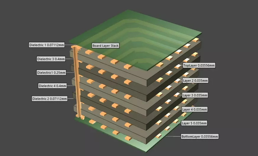
Layer Stack-Up Optimization
In MCPCBs, the layer stack-up often includes a dielectric layer between the copper ground plane and the metal core. The thickness of this dielectric layer impacts both thermal performance and electrical isolation. A thinner dielectric (e.g., 0.1 mm) improves heat transfer but may reduce isolation, while a thicker layer (e.g., 0.2 mm) offers better isolation at the cost of thermal efficiency.
Designers must balance these factors based on the application. For high-power designs, prioritize thermal performance; for sensitive electronics, prioritize isolation.
Ground Plane Thickness
The thickness of the ground plane copper also matters. A thicker ground plane (e.g., 2 oz or 70 μm) offers lower resistance and better heat spreading compared to a thinner plane (e.g., 1 oz or 35 μm). For MCPCBs in high-current applications, opting for a thicker ground plane can significantly improve performance.
Integration with Metal Core
Unlike standard PCBs, MCPCBs allow for direct integration of the ground plane with the metal core in some designs. This can create a highly effective thermal and electrical path but requires careful planning to avoid short circuits or unintended capacitance.
Common Mistakes to Avoid in Ground Plane Design
Even with the best intentions, certain mistakes can undermine the effectiveness of a ground plane in metal core PCBs. Here are some pitfalls to watch out for:
- Splitting the Ground Plane Unnecessarily: This disrupts return paths and increases noise. Only split the plane if isolating analog and digital grounds is critical.
- Insufficient Vias: Failing to use enough vias to connect to the ground plane can lead to high impedance and poor performance.
- Ignoring Thermal Vias: In MCPCBs, thermal vias are essential for connecting the ground plane to the metal core for heat dissipation.
- Overlooking High-Frequency Effects: At frequencies above 100 MHz, small gaps or poor grounding can create significant EMI issues.
By steering clear of these errors, designers can ensure their ground plane performs as intended.
Conclusion: Mastering Ground Plane Design for Metal Core PCBs
The ground plane is a foundational element of any PCB design, and in metal core PCBs, it takes on added significance for noise reduction, heat dissipation, and EMI/RFI shielding capabilities. By focusing on guided ground planes, maintaining a continuous and low-impedance path, and integrating the ground plane with the metal core, designers can create robust and reliable boards for high-power applications.
Whether you’re working on LED systems, power electronics, or automotive components, applying these design principles will help optimize performance and longevity. With careful planning and attention to detail, the ground plane can transform from a simple layer into a powerful tool for enhancing your PCB designs.
At ALLPCB, we’re committed to supporting engineers with the resources and expertise needed to bring their designs to life. By mastering ground plane design, you’re one step closer to creating cutting-edge solutions for your industry.


