ALLPCB


1 Introduction
Modern electronic therapy devices that use two electrode pads placed symmetrically on a treatment area apply a pulsating voltage across the pad-skin interface. The voltage and the local resistance produce a perceptible pulsating current that stimulates nerves and muscles, causing contraction and relaxation to produce a therapeutic effect. Many existing devices generate only a few fixed pulsation patterns. When a treatment area is exposed to a fixed-frequency pulsation for a long time, habituation can occur and involuntary tension may develop, which reduces therapeutic effectiveness. To address this, this design modulates a 2.4 kHz carrier with an audio signal sourced from an MP3 file, producing varying pulsation voltages and changing frequency cycles that follow the dynamics of the audio signal. This allows patients to listen to music during treatment, which may distract attention and reduce tension while applying therapeutic stimulation.
This article presents a design based on the embedded device AT89C51SNDIC and extends it with D/A, mass storage, keypad, and display to implement basic MP3 functions. The AT89C51SNDIC generates audio and a 2.4 kHz mid-frequency carrier. A digital circuit performs frequency modulation of both signals, which are amplified and transformer-isolated to produce the pulsating therapeutic voltage at the electrodes.
2 Working Principle
The hardware structure of the therapy system based on the AT89C51SNDIC is divided into three parts: the signal generation and control module, the frequency-modulated output module, and the power supply module.
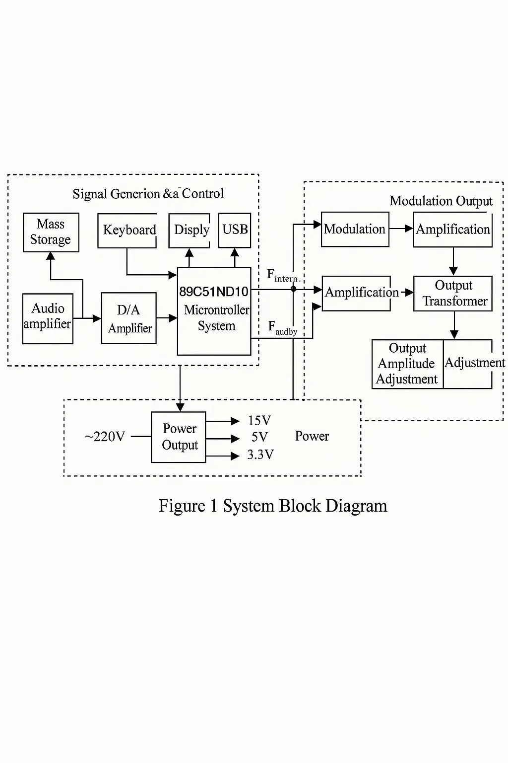
The signal generation and control module comprises the AT89C51SNDIC microcontroller, mass storage, keypad, USB port, LCD display, D/A converter, and audio amplifier. When the device's USB port is connected to a computer USB port, the microcontroller detects the connection and enters USB drive mode, allowing MP3 files to be copied to the device's mass storage. When not connected to a computer, the device functions as an MP3 player. Function keys set track selection, treatment time, and volume; the start/stop key controls the therapy session. During treatment, the microcontroller generates two inverse 2.4 kHz mid-frequency signals (F_mid and F_mid_bar) and an audio signal (F_audio). Stored MP3 tracks are decoded into audio digital data, converted by the D/A, amplified, and sent to headphones or a speaker.
The frequency-modulated output module performs modulation, amplification, output dose adjustment, transformer isolation, and electrode interface. The two inverse mid-frequency signals and the audio signal are modulated to produce two phase-opposite modulated waveforms. After amplification, these signals drive the transformer inputs. The transformer provides isolated pulsating output voltage that is applied to the treatment area via electrode pads; the resulting current varies with the audio modulation. An output dose adjustment allows the delivered current to be adapted to different treatment sites and skin conditions.
The power supply module provides system voltages of 15 V, 5 V, and 3.3 V. When the device is connected to a computer USB port for USB drive use, the microcontroller can be powered by the USB +5 V supply. During therapy, the device is powered from 220 V AC transformed, rectified, regulated, and filtered to provide the required DC voltages.
3 Hardware System Design
3.1 MCU Overview
The AT89C51SNDIC integrates a CPU, MP3 decoder, USB controller, and related functions in a single device. It retains 8051-compatible microcontroller control functionality while supporting MP3 playback and USB drive features. The device is provided in a PLCC package; its internal block diagram is shown in Figure 2.
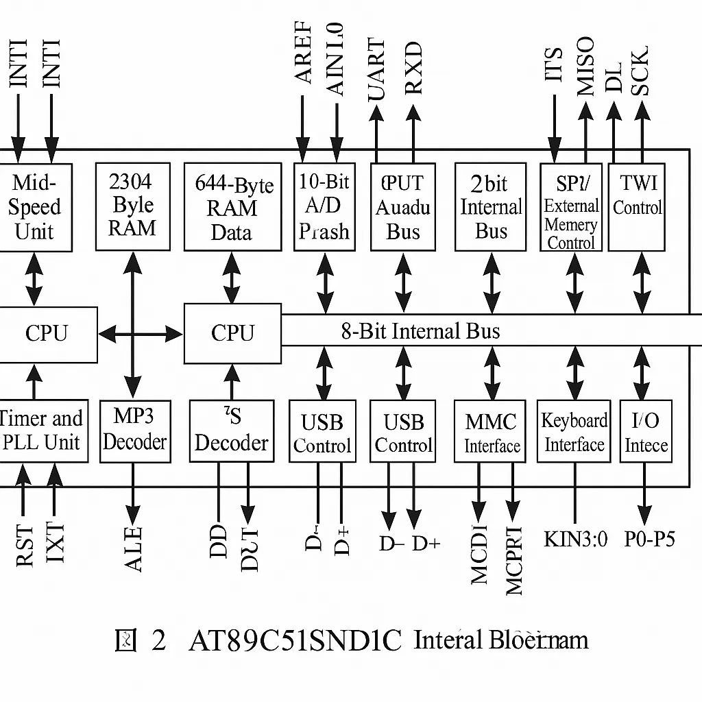
The AT89C51SNDIC has P0, P1, and P3 ports compatible with 51-series microcontrollers, and adds an 8-bit P4 port and a 4-bit P5 port. The clock and reset circuits connect in the same manner as standard 51-series devices.
On first use, the USB driver and the user program must be downloaded separately. The AT89C51SNDIC contains 64 KB ROM; addresses F000H–FFFFH include a preloaded 4 KB boot loader. The factory sets the BLJB bit to 1 so that on power-up the boot loader executes and waits for a download of the USB driver or user code via USB. After downloading, the BLJB bit should be cleared to 0 in the download software and the device power-cycled to run the user program. To update the user program, pull the ISP pin low; after reset the boot loader will run and wait for a new user program. To restart the user program, return the ISP pin to high.
3.2 Signal Generation and Control Module
The circuit block diagram for the signal generation and control module is shown in Figure 3. To implement MP3 and USB drive functions, the AT89C51SNDIC requires an external NAND-Flash mass storage device; a 16 MB K9F2808U0C is used here. Its data lines I/O0–I/O7 connect to the P0 port, and control lines connect to P5. The microcontroller's DOUT, DLCK, DSEL, and SCLK pins connect to a CS4330 D/A converter; after amplification the D/A output feeds headphones or a speaker for MP3 playback. The LCD connects to P2 and works with the keypad to display the device state. The keypad has four keys: a multifunction key for volume/track/timer connected to P1.0, a next key on P1.1, a previous key on P1.2, and a start/stop key on P1.3.
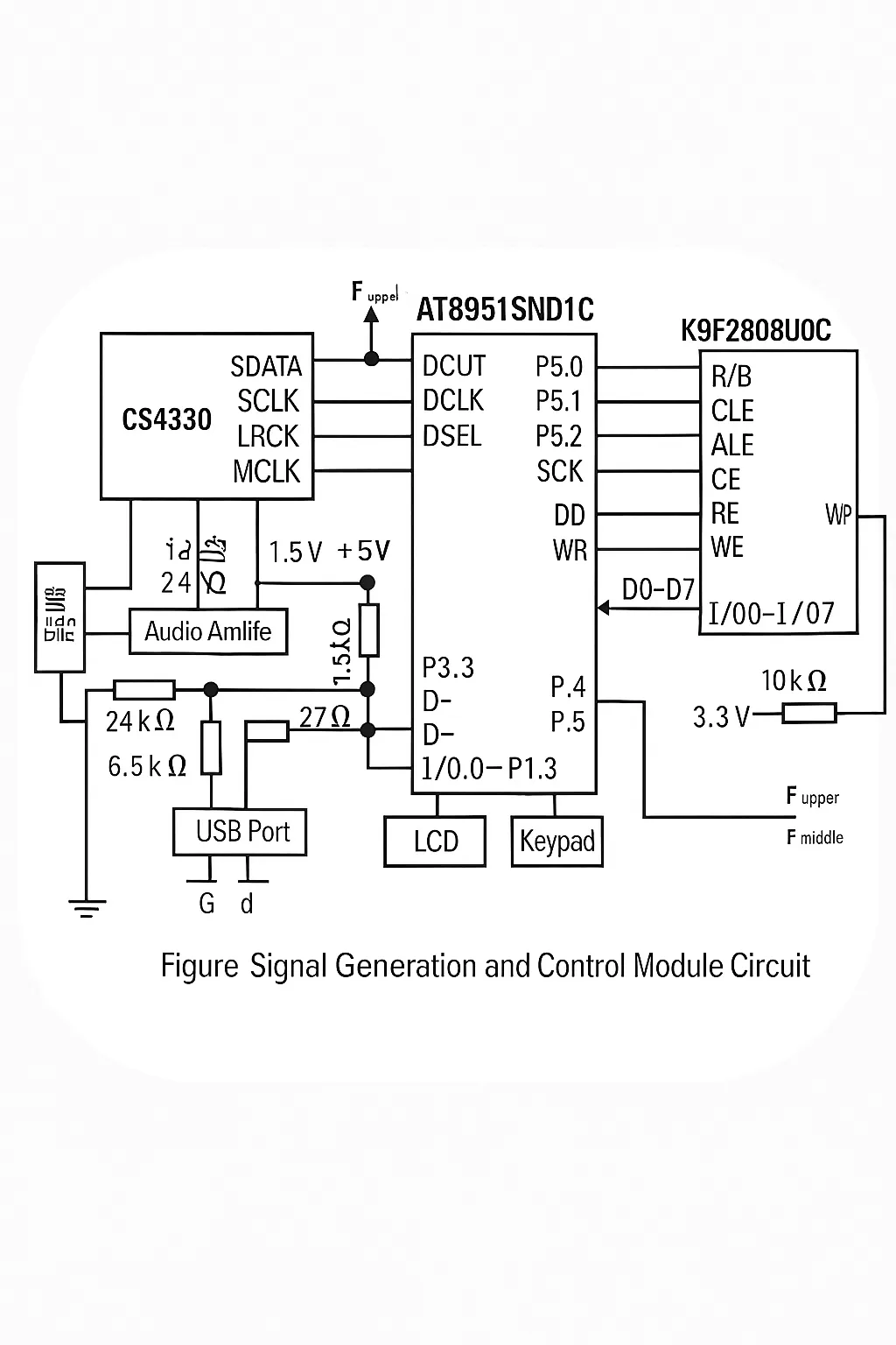
P3.3 of the AT89C51SNDIC detects whether the device is in USB drive mode or MP3 player mode. If the device USB plug is connected to a computer USB port, P3.3 senses a high level and the microcontroller runs the USB drive program; in this case the microcontroller is powered from the USB interface. Otherwise, P3.3 senses a low level and the device runs the MP3 player program. The mid-frequency signals F_mid, F_mid_bar and the audio signal F_audio are routed from the microcontroller to the modulation and output circuitry.
3.3 Frequency-Modulated Output Module
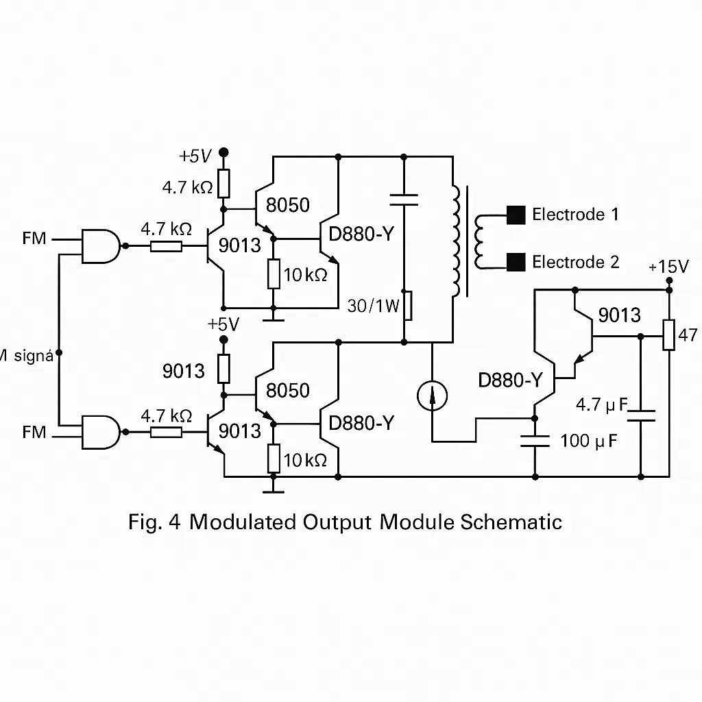
The frequency-modulated output module schematic is shown in Figure 4. The audio signal F_audio modulates the mid-frequency signals F_mid and F_mid_bar, producing two phase-opposed modulated waveforms. These are amplified by transistors 9013, 8050, and D880Y, then fed to the two inputs of a transformer. The transformer center-tap voltage is adjusted via a dose adjustment circuit that includes a milliammeter. A 47 kΩ potentiometer serves as the dose adjustment; decreasing its setting reduces the current indicated by the milliammeter, and increasing it raises the indicated current. The transformer provides isolation and the output voltage waveform follows the input modulation. The output voltage applied through electrode pads generates the perceptible current in the body. Because current perception varies by treatment site and skin moisture, the potentiometer is adjusted until the patient feels comfortable.
3.4 Power Supply Module
The power supply module provides the required 3.3 V, 5 V, and 15 V rails; the schematic is shown in Figure 5. The 3.3 V rail powers the AT89C51SNDIC. The 5 V rail supplies the modulation and amplification circuits; the 15 V rail supplies the output dose adjustment circuit. The 5 V regulator uses a 78L05, and the 3.3 V regulator uses an LD1117S33. When using the USB drive function with the USB port connected to a computer and without connecting to AC mains, the microcontroller power is provided by the USB interface.

4 System Software Design
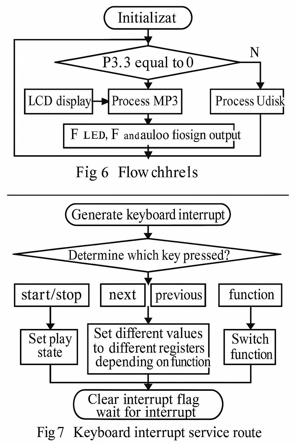
The system software coordinates with the hardware functions; the overall software flowchart is shown in Figure 6. The keyboard interrupt service routine flowchart is shown in Figure 7.
5 Conclusion
The portable device battery monitoring system design uses the programmable battery monitor BQ27210 and an external high-integration processor C8051F304 to implement real-time monitoring of battery capacity, remaining run time, temperature, and voltage. Data is transmitted and processed over an I2C bus. The solution offers high accuracy, small size, and low cost, and has been applied in some handheld data acquisition devices.