ALLPCB


Abstract
Electrocardiogram (ECG) signals are among the earliest studied and clinically applied bioelectrical signals. Compared with other biosignals, ECG is easier to detect and shows clearer periodic patterns. Because cardiac conditions can be sudden or chronic, long-term ECG monitoring has important clinical value. Extended recordings can capture transient abnormalities that are unlikely to appear during routine ECG exams, providing essential data for diagnosis. Early ECG monitors in the 1960s measured a single parameter. With the advent of large-scale integrated circuits and microprocessors, modern monitors can measure multiple parameters. Due to the difficulty of interpreting ECG signals and the specialized nature of monitoring procedures, ECG monitoring is often limited to hospitals and health facilities, making continuous daily monitoring impractical for many patients.
Introduction
Wearable medical devices typically include modules for physiological signal detection and processing, feature extraction, and data transmission, enabling noninvasive continuous monitoring, diagnosis, and therapy. Traditional ECG monitors connect hardware modules with cables and are based on wired platforms. Although suitable for settings such as hospitals and clinics, they are not integrated with common personal communication terminals such as mobile phones, handheld computers, or laptops. This work designs and implements a compact, comfortable, wearable wireless ECG recorder that preserves signal acquisition quality. The design uses the low-power ECG front-end ADS1191 and the low-power microcontroller MSP430F2112 for signal acquisition. Collected ECG signals are transmitted to a communication terminal over Bluetooth for display and analysis. Wireless transmission and wireless charging allow the device to be fully sealed for waterproofing and to meet medical safety requirements.
1 System architecture and design
The wearable wireless ECG recorder must be low-power, compact, and fast. The electrodes used in this study measure roughly 30–75 mm. Considering electrode adhesive support, the expected device thickness is about 0.5 cm and the weight < 30 g. Analog tests show that typical adhesive electrodes can support this size and weight and remain attached during motion.
The ECG recorder consists of an electrode-attachment connection module, ECG front end, main control unit, Bluetooth module, wireless charging module, lithium battery, voltage regulation, and power-management components.
1.1 ECG data acquisition (Module A)
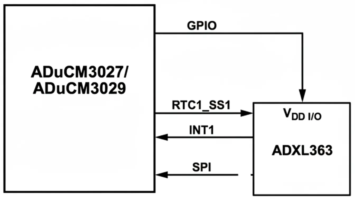
Surface ECG signals are low amplitude and vulnerable to interference. The module preamplifies the acquired ECG using a differential amplifier with high input impedance to suppress baseline drift and reduce common-mode interference. After further amplification (approximately 1000×), interference is filtered and the signal level is raised before passing to the main controller. This module uses TI's low-power ECG front-end ADS1191 to filter, amplify, and A/D convert the ECG, then sends data via SPI to the low-power microcontroller MSP430F2112 for further processing. Wireless transmission uses a compact HM-6 Bluetooth module suitable for handheld devices.
1.2 Power section (Module B)
Wireless charging is derived from wireless power transfer technology. Main wireless charging methods include electromagnetic induction, radio-frequency transmission, and resonant coupling. The wireless charging module uses the Qi standard and the BQ24201 charger. Qi is a standardized wireless charging specification developed by the Wireless Power Consortium (WPC). Qi uses magnetic resonance between the charger and the device to transfer energy through air; coils and capacitors form a resonant pair to enable efficient energy transfer. The BQ24201 is a charger for lithium-ion or lithium-polymer batteries that integrates high-precision voltage regulation, MOSFETs, temperature monitoring, charge-state and termination circuits, reducing external component count and saving space.
The power-management module uses BQ24312 as a front-end protection solution for the lithium-ion charger, providing 4.25 V overvoltage protection. ADuM5000 is used for power isolation; it is an isolated DC/DC solution from ADI that provides an isolated 5 V supply for downstream circuits. Based on the requirement to support > 4 h of continuous ECG acquisition and transmission, the design uses a 90 mAh rechargeable lithium battery. The battery, through a MIC5205 voltage regulator, provides stable 3.3 V digital and analog supplies for ADS1191, MSP430F2112, and the Bluetooth module.
1.3 Embedded software design
The software development environment uses IAR Embedded Workbench for MSP430 with C as the implementation language. To meet low-power requirements, the software implements the following power-control strategies:
- Divide software into several relatively independent functional modules, each triggered by interrupts.
- Use software control to place inactive chips into sleep or idle states.
- Optimize module routines to reduce machine cycles and shorten actual running time, thereby reducing system power consumption.
2.1 Implementation
The recorder is divided into two main parts, each with a diameter of approximately 30 mm, thickness about 5 mm, overall length about 10 cm, and weight 25 g. Interconnects include ground and power lines. Electrode snaps are embedded on the back of the adhesive electrodes and attach directly to the recorder during use. Electrode placement is approximately 3 cm below the left mid-clavicular line, as shown in Figure 5.
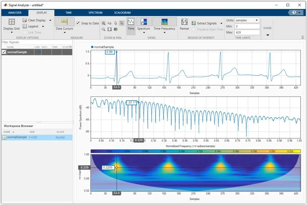
The ECG acquisition front end ADS1191 and the MSP430F2112 draw 0.98 mA during operation; continuous Bluetooth data transmission consumes 16 mA. After preprocessing such as denoising and smoothing, the waveform is stable with minimal baseline drift. P, QRS, and T wave features are clearly visible and suitable for arrhythmia analysis.
2.2 System testing
(1) Input impedance. A signal generator produced a 100 mV 10 Hz sine wave in series with a 620 kΩ resistor connected to the ECG input. Measured generator output amplitude U = 98.8 mV and recorder input voltage U = 95.84 mV; calculated input impedance R = 20.07 MΩ. Relevant national ECG standards specify input impedance ≥ 2.5 MΩ. The recorder's input impedance meets this requirement.
(2) Frequency response. The signal generator swept frequency from 0.1 Hz to 150 Hz while maintaining 100 mV amplitude. The recorder output was recorded using an oscilloscope or recording instrument to obtain the frequency response. Measured gain variation across 0.1–150 Hz was 2.37 dB, less than the 3 dB limit in applicable standards.
(3) Common-mode rejection ratio (CMRR). CMRR is the ratio of differential-mode gain to common-mode gain and indicates interference rejection. A 1.5 V 50 Hz signal was applied as a common-mode input with the input shorted; the output amplitude was recorded and compared with the differential-mode gain. Calculated CMRR = 106.4 dB, meeting national ECG standards.
3 Conclusion
The designed portable ECG recorder is low-power and compact, with these characteristics: 1) simple operation and measurement and low cost; 2) noninvasive, safe, accurate, and repeatable measurements; 3) real-time waveform display; 4) wireless charging capability. Following industrialization, this recorder could be widely used for long-term real-time ECG monitoring.