 ALLPCB


Reflow soldering is a cornerstone of modern electronics manufacturing, especially for surface-mount technology (SMT). One of the most critical aspects of this process is component placement, which directly impacts the quality and reliability of the final product. Proper component placement for reflow soldering, combined with precise solder paste application and controlled preheating (where the temperature gradually increases to around 150°C to 200°C), ensures strong, reliable solder joints. In this comprehensive guide, we'll dive deep into the best practices for component placement, explore the intricacies of solder paste application, and explain the importance of preheating in achieving optimal results.
Whether you're an engineer, a hobbyist, or a manufacturer, understanding these elements will help you improve your PCB assembly process. Let's explore each step in detail to ensure your reflow soldering process is efficient and effective.
What is Reflow Soldering and Why Does Component Placement Matter?
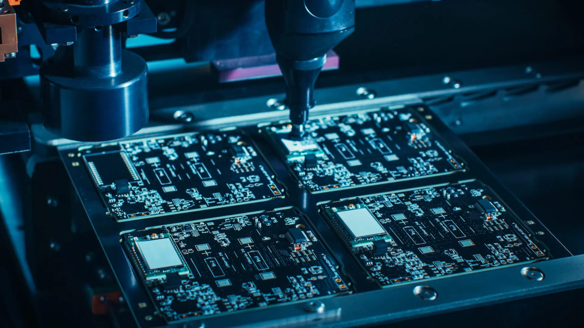
Reflow soldering is a process used to attach surface-mount components to printed circuit boards (PCBs) by melting solder paste. The process involves applying solder paste to the PCB, placing components onto the paste, and then heating the assembly in a controlled manner to create permanent electrical connections. Component placement is a pivotal step because even a slight misalignment can lead to soldering defects like tombstoning, bridging, or insufficient solder joints, which can compromise the functionality of the board.
Accurate placement ensures that components align perfectly with the solder pads, allowing the molten solder to form reliable connections during the reflow process. It also minimizes the risk of defects during preheating and reflow phases, where temperatures are carefully ramped up to prevent thermal shock. Now, let’s break down the key factors and best practices for component placement and related processes.
Key Factors in Component Placement for Reflow Soldering
Component placement isn’t just about putting parts on a board; it requires precision and attention to detail. Below are the essential factors to consider for successful reflow soldering.
1. Precision in Alignment
Components must be placed accurately on the solder pads to ensure proper contact with the solder paste. Misalignment can cause issues like open circuits or short circuits after reflow. Modern pick-and-place machines can achieve placement accuracy within 0.01 mm, which is critical for high-density PCB designs with tiny components like 0201 resistors or fine-pitch ICs.
Tip: Always use design files (like Gerber files) to program automated placement equipment for consistency. For manual placement, use magnification tools to align components precisely.
2. Component Orientation
Pay attention to the orientation of polarized components like diodes, capacitors, and ICs. Incorrect orientation can lead to circuit failure. Most components have markings (like a dot or line) to indicate pin 1 or polarity, which should match the PCB silkscreen or design layout.
3. Spacing and Clearance
Ensure adequate spacing between components to prevent solder bridging, where excess solder connects adjacent pads. Follow the design guidelines for minimum clearance, often around 0.2 mm to 0.3 mm for small components, depending on the solder paste stencil design and component size.
Solder Paste Application: The Foundation of Reflow Soldering
Solder paste application is a crucial step that directly affects component placement and the overall reflow process. Solder paste, a mixture of tiny solder particles and flux, acts as the adhesive that holds components in place before reflow and forms the electrical connection after melting.
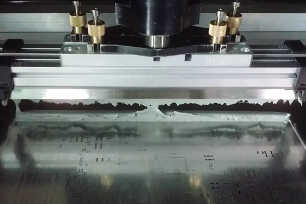
1. Stencil Design and Application
Solder paste is typically applied using a stencil, a thin metal sheet with cutouts corresponding to the PCB pads. The stencil ensures that the right amount of paste is deposited on each pad. A stencil thickness of 0.1 mm to 0.15 mm is common for most SMT assemblies, though this can vary based on component size and pitch.
Best Practice: Use a stencil with rounded aperture corners to ensure even paste release and prevent clogging. Apply the paste using a squeegee at a 45-degree angle for uniform distribution.
2. Volume Control
Too much solder paste can cause bridging, while too little can result in weak joints. The volume of paste should cover about 80-90% of the pad area for optimal results. Inspect the paste application visually or with automated optical inspection (AOI) systems to catch inconsistencies early.
3. Paste Type and Composition
Choose a solder paste that matches your reflow profile and component requirements. Lead-free solder pastes, often made of tin-silver-copper (SAC) alloys, typically have a melting point around 217°C to 220°C. The flux in the paste helps clean the surfaces and improve wetting during reflow, so select a paste with the appropriate activity level (e.g., no-clean or water-soluble flux).
The Role of Preheating in Reflow Soldering
Preheating is the first stage of the reflow soldering process, where the temperature gradually increases to around 150°C to 200°C. This phase is essential for preparing the PCB assembly for the higher temperatures of reflow while minimizing thermal stress on components.
1. Purpose of Preheating
During preheating, the PCB, components, and solder paste are brought to a uniform temperature. This step serves several purposes:
- Reduces Thermal Shock: Sudden temperature changes can crack components or warp the PCB. A gradual ramp-up, typically at a rate of 1-3°C per second, prevents such damage.
- Activates Flux: The flux in the solder paste begins to activate at around 150°C, cleaning the surfaces of pads and component leads for better solder wetting.
- Evaporates Solvents: Volatile solvents in the solder paste are expelled during preheating, reducing the risk of voids or defects in the final solder joint.
2. Temperature Range and Control
The preheating phase generally targets a temperature range of 150°C to 200°C, depending on the solder paste and components used. This range ensures that the assembly is ready for the soak zone (where temperatures stabilize before reflow) without exceeding the thermal limits of sensitive components. For instance, some capacitors and LEDs have maximum temperature ratings that must be respected during preheating.
Tip: Use a reflow oven with multiple heating zones to control the temperature ramp rate precisely. Monitor the process with a thermal profiler to ensure consistency across the board.
Best Practices for Component Placement During Reflow Soldering
To achieve high-quality solder joints and minimize defects, follow these best practices for component placement and the associated reflow soldering steps.
1. Use Automated Equipment for High-Volume Production
For large-scale manufacturing, automated pick-and-place machines are indispensable. These systems can place thousands of components per hour with high accuracy, reducing human error and ensuring consistent results. Program the machine with the correct placement coordinates and verify the setup with a test run before full production.
2. Verify Component Placement Before Reflow
After placement, inspect the board to confirm that all components are correctly aligned and seated on the solder paste. Automated optical inspection (AOI) systems can detect misalignments or missing components with precision, saving time and reducing rework.
3. Optimize Reflow Profile for Preheating and Beyond
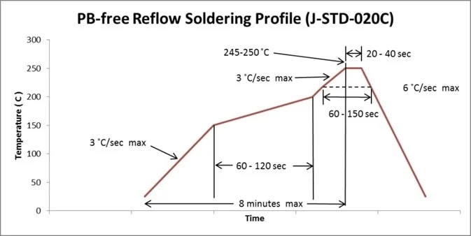
A well-designed reflow profile is critical for successful soldering. During preheating, maintain a steady temperature increase to reach 150°C to 200°C over 60-90 seconds. Follow this with a soak zone to stabilize the temperature, then ramp up to the peak reflow temperature (often 240°C to 250°C for lead-free solder) to melt the paste. Finally, cool the assembly gradually to solidify the joints without stress.
Data Point: A typical lead-free reflow profile might include a preheating ramp rate of 1.5°C/second, a soak time of 60 seconds at 180°C, and a peak temperature of 245°C for 20-30 seconds.
4. Handle Sensitive Components with Care
Some components, like moisture-sensitive devices (MSDs), require special handling before reflow soldering. Store these components in moisture-barrier bags with desiccants and bake them at 125°C for 24 hours if exposed to humidity, as per industry standards. This prevents popcorn defects (cracking due to trapped moisture) during preheating and reflow.
Common Challenges in Component Placement and Solutions
Even with careful preparation, challenges can arise during component placement and reflow soldering. Here are some common issues and how to address them.
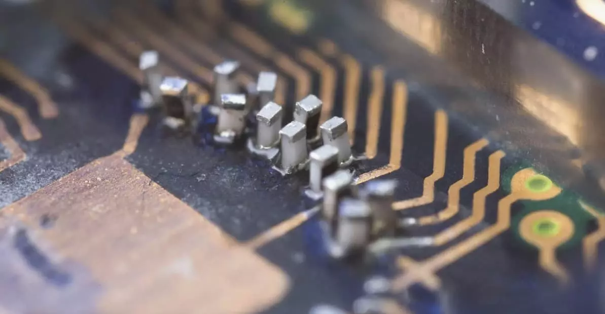
1. Tombstoning
Tombstoning occurs when a small component, like a resistor, stands on one end due to uneven heating or solder paste application. To prevent this, ensure uniform solder paste volume on both pads and design the reflow profile with a balanced preheating phase to avoid rapid temperature differences across the board.
2. Solder Bridging
Bridging happens when excess solder connects adjacent pads, often due to over-application of paste or insufficient spacing. Use a properly designed stencil and maintain adequate clearance in the PCB layout to minimize this risk.
3. Component Shift
Components may shift during reflow if the solder paste isn’t tacky enough or if the board experiences vibration. Use a high-quality paste with good tackiness and secure the board during the reflow process to prevent movement.
Conclusion: Mastering Component Placement for Reflow Soldering
Component placement for reflow soldering is a critical step that sets the stage for a successful PCB assembly. By focusing on precision, proper solder paste application, and controlled preheating (gradually increasing the temperature to around 150°C to 200°C), you can achieve reliable solder joints and minimize defects. Whether you're using automated equipment or manual methods, following best practices ensures consistency and quality in your electronics manufacturing process.
From aligning components accurately to optimizing your reflow profile, every detail matters. With the insights and tips provided in this guide, you're well-equipped to tackle the challenges of reflow soldering and produce high-quality PCB assemblies. Keep refining your techniques and monitoring your processes to stay ahead in the ever-evolving world of electronics manufacturing.


