ALLPCB


Introduction
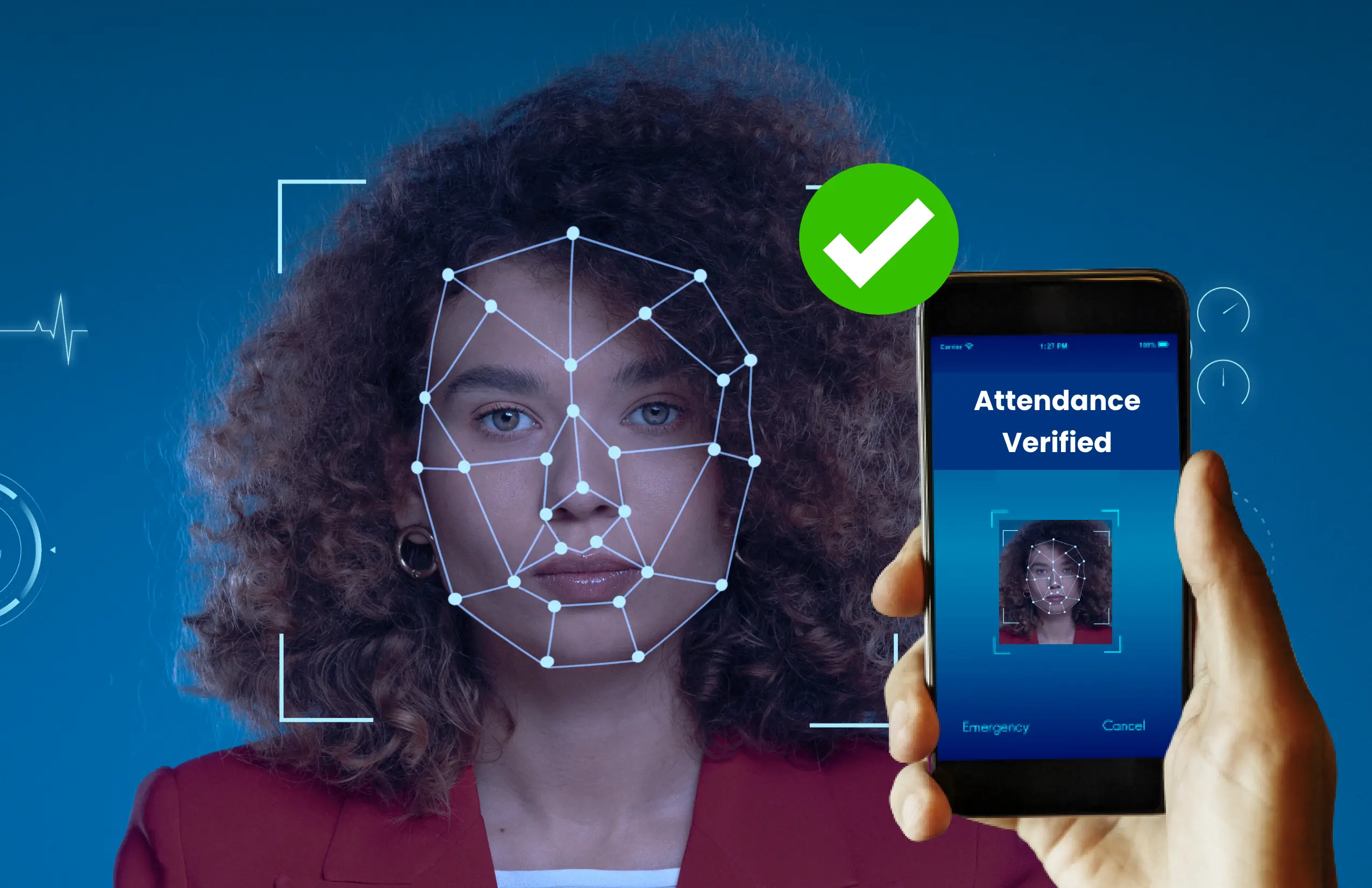
Many identification systems use signatures, fingerprints, voice, hand geometry, or facial recognition to identify people. This project focuses on a facial recognition system.
Facial recognition can be used for security in public spaces and for attendance tracking in offices and schools.
In this project, an ESP32-CAM module is used to build a face recognition system that can act as a security camera by identifying unauthorized persons. The ESP32-CAM is a compact camera module based on the ESP32-S chip. With the ESP32-CAM module, a face recognition system can be built without complex programming or additional components.
ESP32-CAM overview
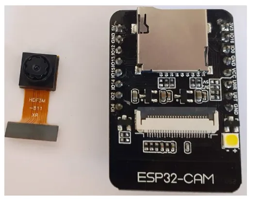
The AI-Thinker ESP32-CAM module includes an ESP32-S chip, a compact OV2640 camera, and a micro SD card slot. The micro SD slot can store images captured by the camera or other files. The ESP32-CAM module is suitable for a variety of IoT applications. It can be used for face detection in offices, schools, and other private areas, and for wireless monitoring, QR code recognition, and other IoT use cases.
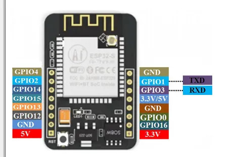
The ESP32-CAM can be programmed with ESP-IDF or Arduino IDE. Several GPIO pins are available for external hardware. The module does not include a USB connector, so a FTDI board is required for programming.
Features
- Small 802.11b/g/n Wi-Fi and Bluetooth SoC module
- Low-power 32-bit CPU that can serve as the application processor
- Clock up to 160 MHz, combined compute up to 600 DMIPS
- Built-in 520 KB SRAM, external 4 MB PSRAM
- Supports UART, SPI, I2C, PWM, ADC, DAC
- Supports OV2640 and OV7670 cameras, built-in flash LED
- Supports image upload over Wi-Fi
- Supports TF card
- Supports multiple sleep modes
- Embedded LwIP and FreeRTOS
- Supports STA, AP, and STA+AP operation modes
- Supports Smart Config and AirKiss
- Supports local and remote serial firmware upgrade (FOTA)
Specifications
- SPI flash: default 32 Mbit
- Memory: 520 KB SRAM + 4 MB PSRAM
- Supports TF card up to 4 GB
- Interfaces: UART, SPI, I2C, PWM
- Image output formats: JPEG, BMP, grayscale
- IO ports: 9
- Power supply: 5 V
Required components
- ESP32-CAM
- FTDI programmer
- Circuit schematic
To build the ESP32-CAM security camera, only the ESP32 camera module and an FTDI programmer are required to upload code to the module.
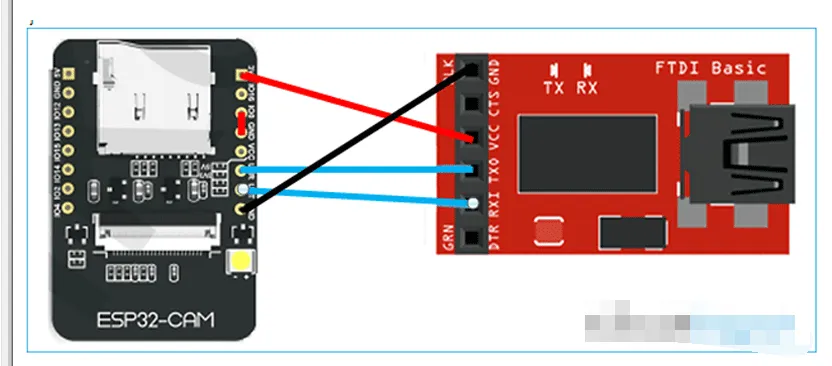
The ESP32-CAM has no USB connector, so an FTDI programmer is needed to upload code. Connect the ESP32 Vcc and GND to the FTDI Vcc and GND. Connect ESP32 Tx to FTDI Rx and ESP32 Rx to FTDI Tx.
Note: Ground IO0 before uploading code. IO0 determines whether the ESP32 enters flash mode. When GPIO0 is connected to GND, the ESP32 is in flash mode.
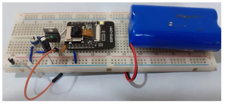
After programming the ESP32, remove the FTDI board and power the module using a 7805 regulator to 3.3 V. The ESP32-CAM video stream setup is shown below.
Install ESP32 board in Arduino IDE
The ESP32-CAM in this guide is programmed using the Arduino IDE. First, install the ESP32 board package in Arduino IDE.
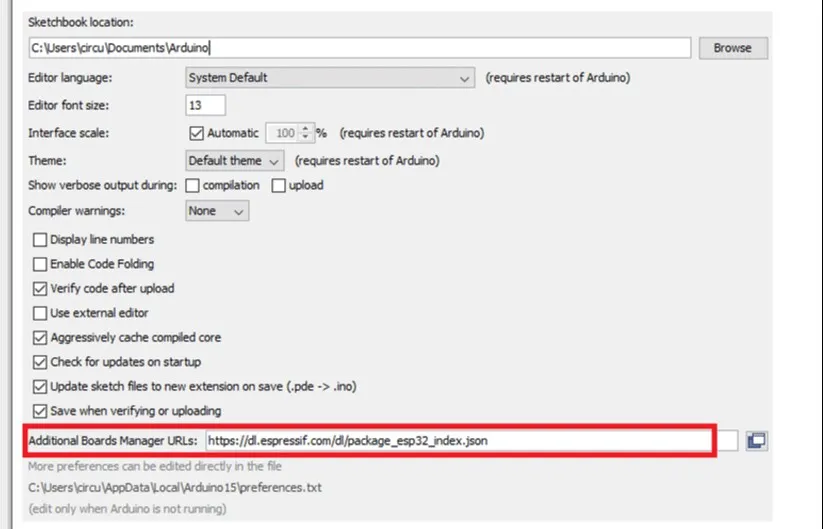
Open File > Preferences and paste the ESP32 board manager URL into the Additional Board Manager URLs field, then click OK.
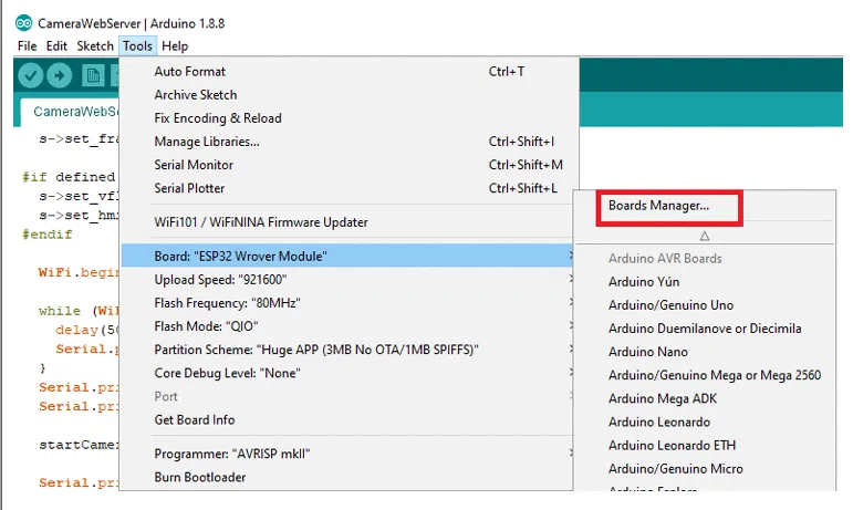
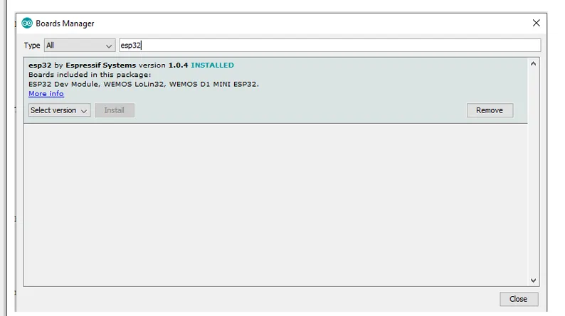
Then go to Tools > Board > Boards Manager, search for ESP32, and install "ESP32 by Espressif Systems".
ESP32 Camera Web Server code
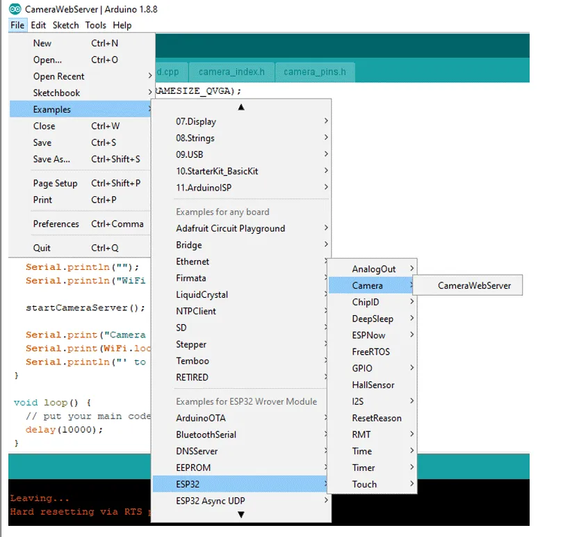
An example for ESP32-CAM video streaming and face recognition is available in the Arduino examples. Open File > Examples > ESP32 > Camera and then open the CameraWebServer example.
Before uploading the code, enter your Wi-Fi name and password in the code.
const char* ssid = "WiFi name";
const char* password = "password";
Then define the ESP camera module. The example includes multiple camera model definitions, so uncomment CAMERA_MODEL_AI_THINKER and comment out the others.
Now the code is ready to upload.
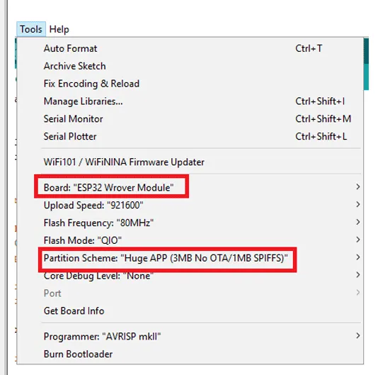
To upload, connect the FTDI board to your laptop and select "ESP32 Wrover Module" as the board. Adjust other settings as shown in the image, then press the ESP32 reset button and click upload.
Note: If you encounter upload errors, verify IO0 is connected to GND and the correct board and settings are selected in the Tools menu.
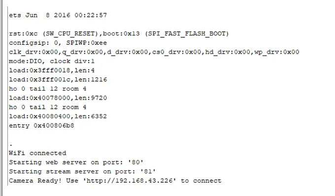
After uploading, disconnect IO0 from GND. Open the serial monitor at 115200 baud, press the ESP32 reset button, and the serial monitor will display the ESP IP address and port.
To access the camera stream, navigate to the ESP IP address in a browser. The streaming page will open. Click the "Start Stream" button at the bottom of the page to begin.
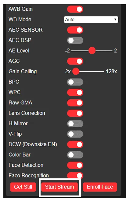
You can change the stream quality from the "Resolution" option on the streaming page. The "Get Still" button captures an image, but the example code does not save images.
After testing the video stream, enable face detection and recognition from the settings page in the web UI.
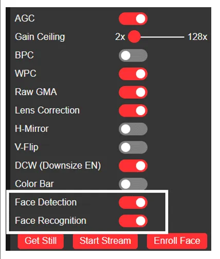
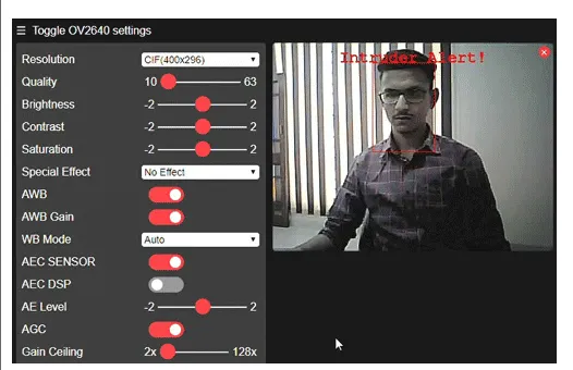
To perform face recognition, register faces first. Click "Register Face" to add a new face. Multiple attempts may be needed to capture a usable face. Once saved, the face is stored as subject 0 and can be used for recognition in the security system.
This demonstrates how the ESP32 camera module can be configured for video streaming and face recognition.
#include <esp_camera.h>

#include <wifi.h>


// WARNING!!! Make sure you have selected the ESP32 Wrover module,
// or another board with PSRAM enabled


// Select the camera model

//#define CAMERA_MODEL_WROVER_KIT

//#define CAMERA_MODEL_ESP_EYE

//#define CAMERA_MODEL_M5STACK_PSRAM

//#define CAMERA_MODEL_M5STACK_WIDE

#define CAMERA_MODEL_AI_THINKER

#include <camera_pins.h>


const char* ssid = "银河-M20";

const char* 密码 = "ac312124";


void startCameraServer();


void setup(){

Serial.begin(115200);

Serial.setDebugOutput(true);

Serial.println();


camera_config_t config;

config.ledc_channel = LEDC_CHANNEL_0;

config.ledc_timer = LEDC_TIMER_0;

config.pin_d0 = Y2_GPIO_NUM;

config.pin_d1 = Y3_GPIO_NUM;

config.pin_d2 = Y4_GPIO_NUM;

config.pin_d3 = Y5_GPIO_NUM;

config.pin_d4 = Y6_GPIO_NUM;

config.pin_d5 = Y7_GPIO_NUM;

config.pin_d6 = Y8_GPIO_NUM;

config.pin_d7 = Y9_GPIO_NUM;

config.pin_xclk = XCLK_GPIO_NUM;

config.pin_pclk = PCLK_GPIO_NUM;

config.pin_vsync = VSYNC_GPIO_NUM;

config.pin_href = HREF_GPIO_NUM;

config.pin_sscb_sda = SIOD_GPIO_NUM;

config.pin_sscb_scl = SIOC_GPIO_NUM;

config.pin_pwdn = PWDN_GPIO_NUM;

config.pin_reset = RESET_GPIO_NUM;

config.xclk_freq_hz = 20000000;

config.pixel_format = PIXFORMAT_JPEG;

// Initialize with high specs to pre-allocate larger buffers

if(psramFound()){

config.frame_size = FRAMESIZE_UXGA;

config.jpeg_quality = 10;

config.fb_count = 2;

} else {

config.frame_size = FRAMESIZE_SVGA;

config.jpeg_quality = 12;

config.fb_count = 1;

}


#if defined(CAMERA_MODEL_ESP_EYE)

pinMode(13,INPUT_PULLUP);

pinMode(14, INPUT_PULLUP);

#endif


// Camera initialization

esp_err_t err = esp_camera_init(&config);

if(err != ESP_OK){

Serial.printf("相机初始化失败,错误 0x%x", err);

return;

}


sensor_t * s = esp_camera_sensor_get();

// Initial sensor is vertically flipped and color is a bit saturated

if (s->id.PID == OV3660_PID) {

s->set_vflip(s, 1); // flip it back

s->set_brightness(s, 1); // increase brightness slightly

s->set_saturation(s, -2); // reduce saturation

}

// Reduce frame size for a higher initial frame rate

s->set_framesize(s, FRAMESIZE_QVGA);


#if defined(CAMERA_MODEL_M5STACK_WIDE)

s->set_vflip(s, 1);

s->set_hmirror(s, 1);

#endif


WiFi.begin(ssid, 密码);


while(WiFi.status() != WL_CONNECTED){

delay(500);

Serial.print(".");

}

Serial.println("");

Serial.println("WiFi 连接");


startCameraServer();


Serial.print("相机准备好了!使用'http://");

Serial.print(WiFi.localIP());

Serial.println("'要连接");

}


void loop(){

// Put your main code here, to run repeatedly:

delay(10000);

}