 ALLPCB


If you're looking for the best ways to replace Ball Grid Array (BGA) components on high-density printed circuit boards (PCBs), you've come to the right place. BGA rework and replacement can be challenging due to the tiny solder balls and compact layouts of modern boards. The key to success lies in using the right tools, following precise techniques, and taking steps to avoid damage to the PCB or components. In this guide, we'll walk you through proven methods for BGA rework, ball grid array replacement, BGA soldering techniques, high-density PCB repair, and advanced component replacement, ensuring you achieve reliable results every time.
Whether you're an experienced engineer or a technician tackling a complex repair, this comprehensive blog post will provide actionable steps, tips, and insights to master the process. Let's dive into the details of handling BGA components on high-density PCBs with precision and care.
What Are BGA Components and Why Are They Challenging to Replace?
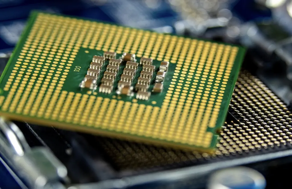
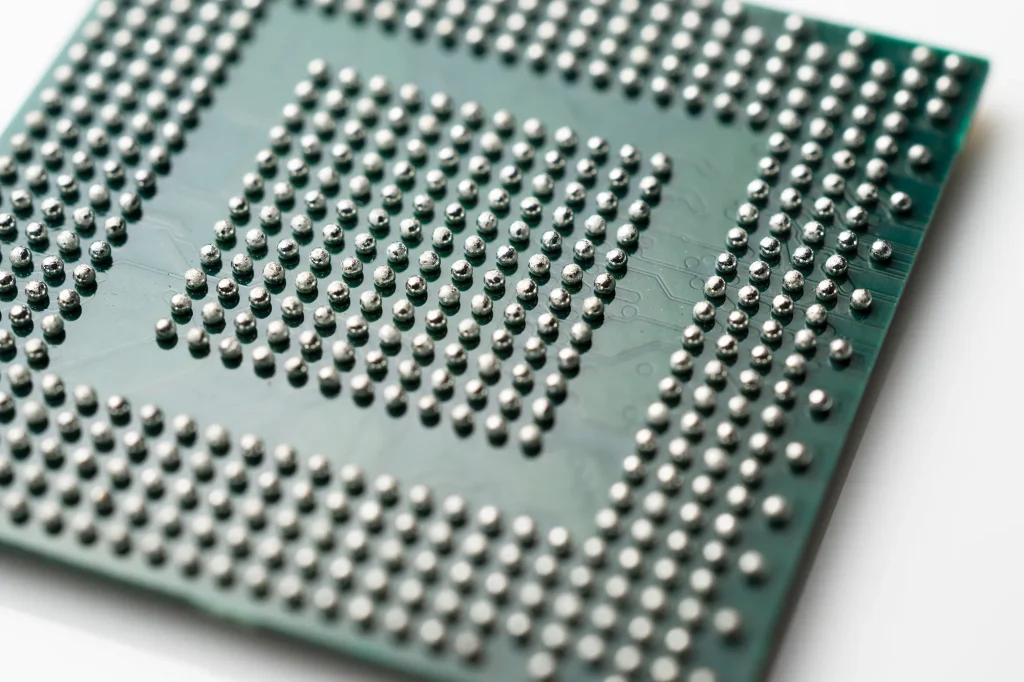
BGA components are a type of surface-mount packaging used for integrated circuits. Unlike traditional components with visible leads, BGAs connect to the PCB using an array of tiny solder balls underneath the package. This design allows for higher pin counts—sometimes exceeding 2000 pins in packages as small as 45mm—making them ideal for compact, high-density PCBs used in smartphones, laptops, and other advanced electronics.
However, replacing BGA components is tricky. The solder balls are hidden beneath the component, making it hard to inspect or access them. High-density PCBs often have multiple layers and tight spacing, increasing the risk of damaging nearby components or traces during rework. Additionally, improper heat application can warp the board or cause thermal stress, leading to long-term reliability issues. Mastering BGA rework requires understanding these challenges and using specialized techniques to overcome them.
Essential Tools for BGA Rework and Replacement
Before starting any ball grid array replacement, ensure you have the right tools. Using improper equipment can lead to damaged components or boards. Here's a list of essential tools for effective high-density PCB repair:
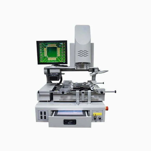
- BGA Rework Station: A dedicated rework station with precise temperature control is critical. These stations often include infrared heaters or hot air systems to evenly heat the component and board. Look for a station with a temperature accuracy of ±2°C to avoid overheating.
- Preheater: A preheater warms the entire PCB to reduce thermal stress during rework. This is especially important for high-density boards with multiple layers, as uneven heating can cause warping.
- Thermocouples: These sensors monitor the temperature of the PCB and component in real-time, ensuring you stay within safe limits (typically 220-240°C for lead-free solder).
- Vacuum Pickup Tool: This tool safely lifts the BGA component after desoldering without applying mechanical stress.
- Solder Paste and Flux: High-quality solder paste and flux are necessary for clean soldering and to prevent defects like voids in the solder joints.
- X-Ray Inspection System: Since BGA solder joints are hidden, an X-ray system helps inspect the quality of the connections after rework.
- Microscope: A stereo microscope with at least 10x magnification helps with precise alignment and inspection of small solder balls (typically 0.3-0.8mm in diameter).
Investing in reliable tools is the first step toward successful advanced component replacement. Without them, even the best techniques can fall short.
Step-by-Step Guide to BGA Rework on High-Density PCBs
Now that you have the tools, let's walk through the process of replacing a BGA component. Following these steps will help ensure a smooth BGA soldering technique and minimize risks.
1. Preparation and Safety
Start by preparing your workspace. Ensure proper ventilation to avoid inhaling fumes from solder or flux. Wear an anti-static wrist strap to prevent electrostatic discharge (ESD), which can damage sensitive components on high-density PCBs. Review the PCB's design files to identify the BGA component's location, surrounding parts, and any heat-sensitive areas.
2. Preheat the PCB
Use a preheater to warm the entire board to about 100-120°C. This reduces the temperature difference between the BGA area and the rest of the board, preventing thermal shock. High-density PCBs often have 6-12 layers, so preheating is crucial to avoid delamination or cracking due to uneven expansion.
3. Remove the Old BGA Component
Set your rework station to the correct temperature profile based on the solder type (lead-free solder typically requires 220-240°C). Use the hot air or infrared heater to melt the solder balls under the BGA. Once the solder is molten (usually after 30-60 seconds), use a vacuum pickup tool to gently lift the component off the board. Avoid excessive force, as this can damage the pads or traces.
4. Clean the PCB Pads
After removal, clean the PCB pads to remove old solder and residue. Use a soldering iron with a fine tip and desoldering braid to wick away excess solder. Apply flux to help with cleaning and prevent oxidation. Inspect the pads under a microscope to ensure they are flat and free of damage. Damaged pads can lead to poor connections during reattachment.
5. Reball or Prepare the New BGA Component
If reusing the old BGA, you may need to reball it by attaching new solder balls. Use a stencil matching the BGA's ball pattern and apply solder paste, then reflow the balls using a rework station. For a new component, ensure the solder balls are intact and properly aligned. This step is critical for reliable ball grid array replacement.
6. Align and Place the BGA Component
Apply a thin layer of flux to the PCB pads to improve solder wetting. Carefully align the BGA component over the pads using a microscope or alignment tool. Many rework stations have built-in cameras for precise placement, ensuring each solder ball (often spaced at 0.5-1.27mm pitch) matches its corresponding pad.
7. Reflow the Solder
Use the rework station to reflow the solder balls. Follow a temperature profile that ramps up gradually to the peak reflow temperature (around 235°C for lead-free solder) over 3-4 minutes, then cools down slowly. This prevents thermal stress and ensures even soldering across all connections.
8. Inspect the Rework
After cooling, inspect the rework using an X-ray system to check for voids, bridging, or misaligned solder joints. Voids larger than 25% of the solder ball area can weaken the connection and affect reliability. If issues are found, you may need to repeat the reflow process or clean and reball the component.
Common Challenges in BGA Rework and How to Overcome Them
Even with the best tools and techniques, high-density PCB repair can present challenges. Here are some common issues and solutions:
- Thermal Damage: Excessive heat can damage the PCB or nearby components. Use a preheater and monitor temperatures with thermocouples to stay within safe limits (below 250°C for most boards).
- Solder Voids: Voids in solder joints reduce reliability. Ensure proper flux application and follow a controlled reflow profile to minimize trapped air or moisture.
- Pad Damage: Overworking the pads during cleaning can lift or damage them. Use minimal heat and gentle pressure with desoldering braid to preserve pad integrity.
- Component Misalignment: Misaligned BGAs lead to open circuits or shorts. Use precise alignment tools and double-check placement before reflow.
Addressing these challenges upfront will save time and prevent costly mistakes during advanced component replacement.
Tips for Ensuring Long-Term Reliability After BGA Replacement
Successful BGA rework isn't just about getting the component back on the board—it's about ensuring the repair lasts. Follow these tips for long-term reliability:
- Use High-Quality Materials: Choose solder paste and flux from reputable suppliers to avoid issues like poor wetting or corrosion over time.
- Control Humidity and Storage: Store BGAs and PCBs in a low-humidity environment (below 30% relative humidity) to prevent moisture absorption, which can cause popcorn defects during reflow.
- Perform Stress Testing: After rework, test the board under operating conditions to verify signal integrity and thermal performance. For high-speed designs, ensure impedance values remain within spec (typically 50 ohms for single-ended traces).
- Document the Process: Keep detailed records of temperature profiles, inspection results, and any issues encountered. This data helps refine future rework processes.
Why Choose Professional Support for BGA Rework?
While DIY BGA soldering techniques are possible with the right skills and tools, complex high-density PCBs often benefit from professional support. Expert services offer advanced equipment like industrial-grade X-ray systems and automated rework stations, ensuring precision and reliability. They also have experience handling intricate designs with tight tolerances, reducing the risk of costly errors.
At ALLPCB, we provide comprehensive solutions for PCB assembly and repair, including specialized support for BGA rework. Our team uses state-of-the-art tools and follows strict quality standards to deliver flawless results, even for the most challenging projects.
Conclusion
Replacing BGA components on high-density PCBs is a complex task, but with the right approach, tools, and techniques, it can be done successfully. By following the best practices outlined in this guide—preparing properly, using precise BGA soldering techniques, addressing common challenges, and ensuring long-term reliability—you can master ball grid array replacement and high-density PCB repair. Whether you're tackling a small repair or a large-scale project, these steps will help you achieve professional-grade results.
Remember that advanced component replacement requires patience and attention to detail. Take your time, invest in quality equipment, and don't hesitate to seek professional assistance for critical or high-value boards. With practice and the right mindset, you'll be well-equipped to handle any BGA rework challenge that comes your way.


