 ALLPCB


If you're dealing with a damaged rigid-flex PCB and wondering how to repair it, the good news is that many issues can be fixed with the right techniques and tools. Rigid-flex PCB repair is possible for common damages like broken traces, cracked solder joints, or delamination, provided you follow a careful, step-by-step process. In this guide, we'll walk you through practical methods for rigid-flex PCB rework, the tools you'll need, and tips to avoid further damage.
Rigid-flex PCBs combine the durability of rigid boards with the versatility of flexible circuits, making them essential in compact, high-performance devices like smartphones, medical equipment, and aerospace systems. However, their unique structure also makes repairs more challenging than standard PCBs. Whether you're an engineer or a technician, this comprehensive guide will equip you with the knowledge to tackle rigid-flex PCB damage effectively. Let's dive into the world of rigid-flex PCB repair techniques and tools to restore your board's functionality.
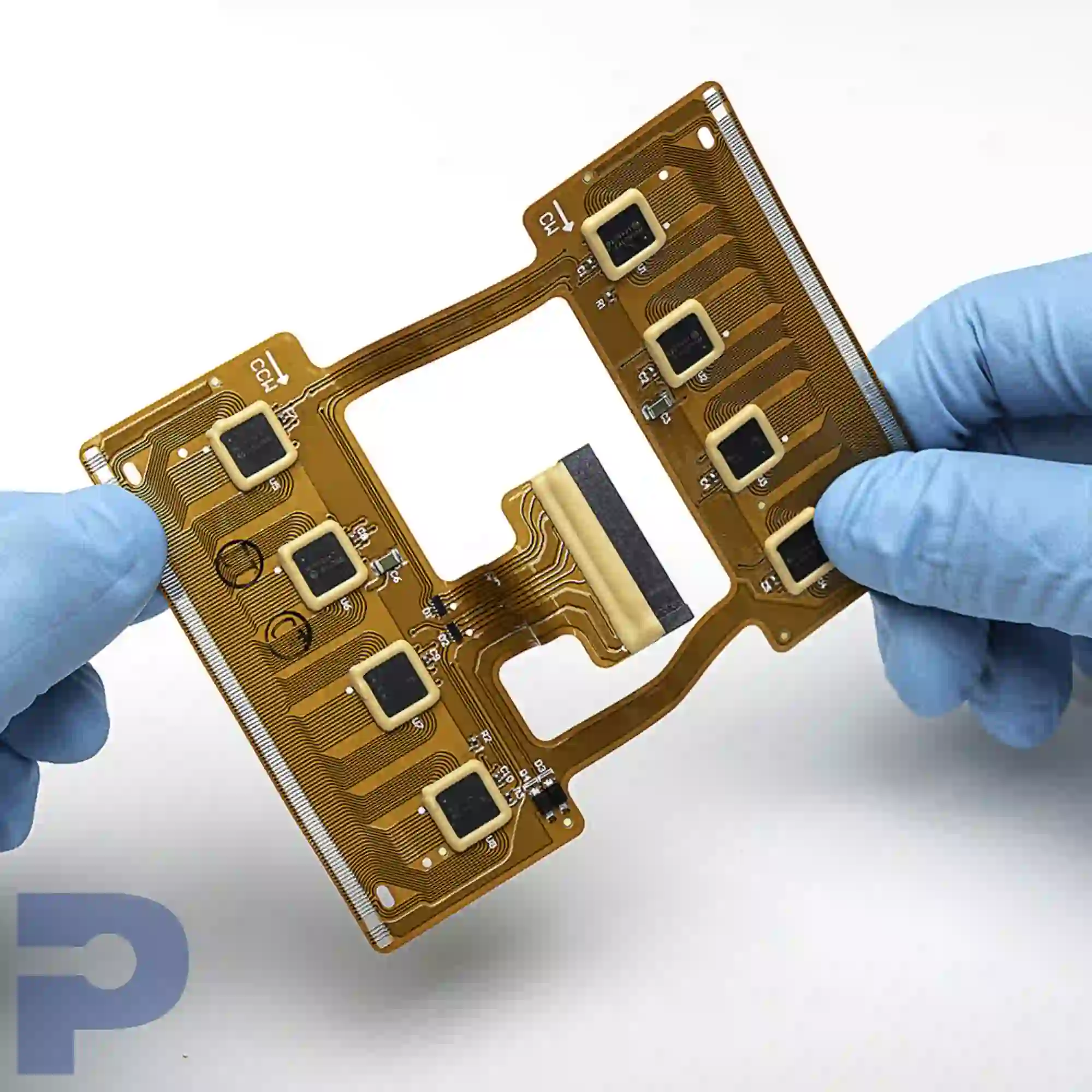
What Are Rigid-Flex PCBs and Why Are They Prone to Damage?
Rigid-flex PCBs are hybrid circuit boards that integrate rigid and flexible sections into a single unit. The rigid parts provide structural support for components, while the flexible sections allow the board to bend or fold, fitting into tight spaces. This design is ideal for modern electronics where space and weight are critical factors.
However, the combination of materials—often FR4 for rigid areas and polyimide for flexible zones—creates stress points at the transitions between rigid and flex areas. These stress points are prone to cracking or delamination under mechanical strain, thermal cycling, or improper handling. For instance, bending a flex section beyond its specified radius (often as low as 10 times the board thickness) can cause permanent damage. Additionally, high-frequency signals, sometimes operating at impedance levels of 50 ohms or more, can be disrupted by even minor trace damage, affecting performance.
Common types of rigid-flex PCB damage include:
- Broken or cracked traces in the flexible areas due to excessive bending.
- Delamination where layers separate, often caused by heat or moisture.
- Damaged solder joints from thermal stress or vibration.
- Physical tears or cuts in the flex section from mishandling.
Understanding these vulnerabilities is the first step in rigid-flex PCB repair. By identifying the type of damage, you can choose the right approach for rework.
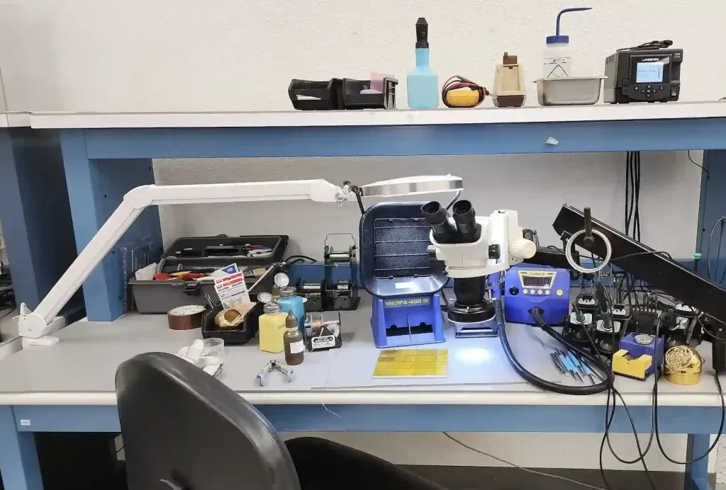
Essential Tools for Rigid-Flex PCB Repair
Before attempting any rigid-flex PCB rework, gather the right tools to ensure precision and avoid further damage. Working on these boards requires a delicate touch, as the flexible sections are particularly sensitive. Here's a list of essential tools for rigid-flex PCB repair:
- Precision Soldering Iron: Use a temperature-controlled soldering iron with a fine tip (0.5mm or smaller) to work on small pads and traces. Set the temperature between 280°C and 320°C to prevent overheating the board.
- Desoldering Tools: A desoldering pump or braid is crucial for removing old solder without damaging pads, especially in tight flex areas.
- Magnifying Equipment: A magnifying glass or a digital microscope (with at least 10x magnification) helps inspect tiny cracks or trace damage invisible to the naked eye.
- Conductive Epoxy or Wire: For repairing broken traces, conductive epoxy or thin jumper wires (30 AWG or finer) can bridge small gaps.
- Multimeter: Essential for testing continuity and identifying broken traces or faulty components. Look for a model with micro-ohm resolution for accurate readings.
- Anti-Static Tweezers: Prevent electrostatic discharge (ESD) damage by using anti-static tools when handling the board.
- Heat Gun: Useful for controlled heating during delamination repairs or component removal. Keep the temperature below 200°C to avoid damaging the flex material.
- Cutting Tools: Precision blades or micro-drills for removing damaged sections of the board without affecting nearby areas.
- ESD Mat and Wrist Strap: Protect sensitive components from static electricity during rigid-flex PCB repair.
Having these rigid-flex PCB repair tools on hand ensures you can address a variety of damages, from trace breaks to component failures, with minimal risk to the board.
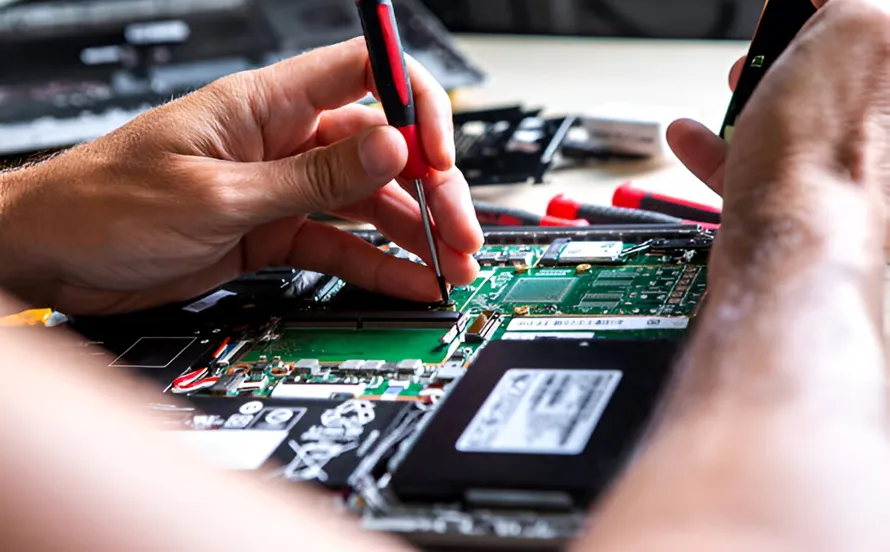
Step-by-Step Rigid-Flex PCB Repair Techniques
Repairing a rigid-flex PCB requires a systematic approach to avoid worsening the damage. Below, we outline practical rigid-flex PCB repair techniques for common issues like trace damage, delamination, and solder joint failures. Follow these steps carefully for effective rigid-flex PCB rework.
1. Assess the Damage
Start by thoroughly inspecting the board under magnification. Use a digital microscope to check for hairline cracks in the flexible areas, broken traces, or signs of delamination (layer separation). Test for continuity with a multimeter to pinpoint open circuits. For example, a trace in a high-speed data line might show infinite resistance if broken, indicating a need for repair. Document the damage areas to plan your rework strategy.
2. Repairing Broken Traces
Broken traces are a common issue in the flexible sections of rigid-flex PCBs due to bending stress. Here's how to fix them:
- Clean the damaged area with isopropyl alcohol (90% or higher) and a soft brush to remove debris or oxidation.
- If the trace is partially intact, scrape away the protective coating (solder mask) with a precision blade to expose the copper.
- Apply a small amount of conductive epoxy or solder a thin jumper wire (30 AWG) to bridge the gap. Ensure the connection aligns with the original trace path to maintain signal integrity, especially for high-frequency signals at 50 ohms impedance.
- Insulate the repair with a thin layer of UV-curable epoxy or kapton tape to prevent short circuits.
Note: For multi-layer boards, trace repair might require accessing internal layers, which is more complex and may need professional equipment like X-ray imaging to locate the fault.
3. Fixing Delamination
Delamination occurs when layers of the PCB separate, often due to heat or moisture. To repair it:
- Use a heat gun at low temperature (around 150°C) to soften the adhesive between layers. Avoid excessive heat, as polyimide flex materials can degrade above 200°C.
- Inject a small amount of epoxy adhesive into the separated area using a fine syringe. Spread it evenly with gentle pressure.
- Clamp the area lightly with a padded vice or weights and let it cure for 24 hours as per the epoxy manufacturer's instructions.
This method works best for small delaminated areas. Extensive delamination may render the board irreparable.
4. Repairing Damaged Solder Joints
Cracked solder joints often result from thermal stress or vibration. To rework them:
- Remove old solder using a desoldering braid and a soldering iron set to 300°C. Avoid prolonged heat exposure to prevent lifting pads.
- Clean the pad with isopropyl alcohol and inspect for damage. If the pad is lifted, secure it with a small dab of epoxy before resoldering.
- Resolder the joint with fresh lead-free solder, ensuring a shiny, concave fillet for a strong connection. A typical soldering time should be under 3 seconds per joint to minimize heat stress.
5. Testing Post-Repair
After completing the rigid-flex PCB repair, test the board thoroughly. Use a multimeter to check for continuity across repaired traces and joints. If the board is part of a larger system, power it up in a controlled environment to verify functionality. For high-speed circuits, consider using an oscilloscope to ensure signal integrity, checking for distortions or delays beyond acceptable limits (e.g., 100 ps for a 5 GHz signal).
Common Challenges in Rigid-Flex PCB Rework
Rigid-flex PCB damage presents unique challenges due to the board's hybrid nature. Here are some common issues and how to address them during repair:
- Heat Sensitivity: Flexible materials like polyimide can warp or burn under high temperatures. Always use low-heat settings and work in short bursts when soldering or using a heat gun.
- Fragile Flex Sections: Excessive bending during repair can worsen cracks. Secure the board on a stable, padded surface to minimize movement.
- Signal Integrity Issues: Repairs to high-speed traces must maintain impedance (often 50 or 75 ohms). Avoid long jumper wires or uneven epoxy applications that could introduce noise or signal loss.
- Multi-Layer Complexity: Internal layer damage in multi-layer rigid-flex PCBs is hard to access. Specialized tools like micro-drills or professional rework stations may be necessary for such cases.
Being aware of these challenges helps you approach rigid-flex PCB rework with caution and precision, increasing the likelihood of a successful repair.
Tips to Prevent Future Rigid-Flex PCB Damage
While rigid-flex PCB repair techniques are valuable, prevention is always better than rework. Here are actionable tips to extend the lifespan of your boards:
- Handle the boards with care, avoiding sharp bends beyond the manufacturer's specified radius (often 10-20 times the flex thickness).
- Store rigid-flex PCBs in a dry, temperature-controlled environment to prevent moisture-induced delamination. Ideal storage conditions are 20-25°C with 40-50% humidity.
- Use proper mounting techniques to minimize mechanical stress on flex areas during assembly.
- Design with durability in mind, ensuring transition zones between rigid and flex sections have adequate reinforcement or strain relief.
Implementing these practices reduces the need for frequent rigid-flex PCB repair and ensures reliable performance in your applications.
When to Seek Professional Help for Rigid-Flex PCB Repair
Not all rigid-flex PCB damage can be fixed with basic tools and techniques. In some cases, seeking professional help is the best option to avoid further issues. Consider professional rework services if:
- The damage involves internal layers of a multi-layer board, requiring advanced imaging or micro-drilling.
- High-frequency signal paths are affected, and you lack the equipment to test or restore impedance matching.
- The board is part of a critical system (e.g., medical or aerospace) where reliability is non-negotiable, and repairs must meet strict standards like IPC-7711/7721 for rework and repair.
Professional services have access to specialized rigid-flex PCB repair tools and expertise, ensuring a higher success rate for complex damages.
Conclusion: Mastering Rigid-Flex PCB Repair
Repairing damaged rigid-flex PCBs is a delicate but achievable task with the right knowledge, tools, and techniques. By understanding the unique structure of these boards, identifying common types of rigid-flex PCB damage, and following systematic rigid-flex PCB repair techniques, you can restore functionality to your boards and avoid costly replacements. Whether you're fixing broken traces, addressing delamination, or repairing solder joints, precision and patience are key to successful rigid-flex PCB rework.
Equipping yourself with essential rigid-flex PCB repair tools like precision soldering irons, multimeters, and magnifying equipment sets the foundation for effective repairs. Additionally, taking steps to prevent future damage through proper handling and storage can save you time and effort in the long run. For complex issues beyond your expertise, don't hesitate to consult professionals to ensure the board meets performance and safety standards.
With this practical guide, you're now better prepared to tackle rigid-flex PCB repair challenges. Keep practicing these methods, and over time, you'll gain confidence in handling even the most intricate rework tasks.


