ALLPCB


Overview
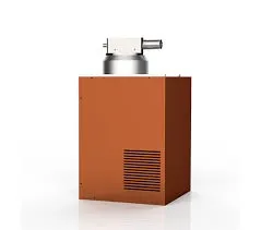
An ultrasonic sensor uses ultrasonic waves and typically employs a piezoelectric element that can both emit and receive sound. Sensors used for detection come in different structures such as single probe, dual probe, and angled probe. The piezoelectric element materials and thicknesses vary by design.
Distance Measurement Principle
The distance measurement principle uses an ultrasonic transmitter to emit sound waves. When the waves encounter an obstacle they return, and the distance from the transmitter to the obstacle is calculated from the wave propagation speed and the return time. This is the time-of-flight method. Ultrasonic waves are affected by temperature and pressure, but temperature effects can be neglected when temperature variation is small. For higher accuracy, temperature compensation should be applied.
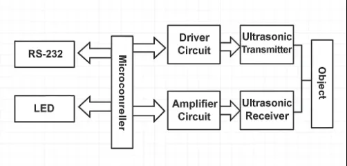
Hardware Composition
The ultrasonic transmission circuit consists of transistors, resistors, a T/R40-16 piezoelectric ceramic ultrasonic transducer, and a transformer. Based on available information, ultrasonic waves around 40 kHz have the best propagation efficiency in air. The working principle is illustrated below:
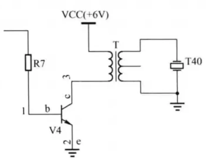
On startup, the microcontroller initializes ports via software so that pin RA2 is low; in this state the ultrasonic transmission circuit is off. After initialization, the microcontroller drives RA2 high so the transistor collector goes low; the transformer steps up this voltage and applies it across the ultrasonic transducer T40, producing ultrasonic waves. If a target is within the effective measurement sector, the echo from a previous transmission should be received before the next transmission; otherwise no obstacle is detected in that direction. The system maximum measurement range is 9.99 m, so the pulse interval is t = 2s/v = 2×9.99 m / 340 m/s = 59 ms.
The ultrasonic reception circuit consists of the receiving transducer and a three-stage amplification and filtering circuit. Because echoes are weak at greater distances, the transducer output amplitude can be small and requires amplification. When the receiving transducer detects an ultrasonic echo, the signal passes through the three-stage amplifier, and pin R40 changes from low to high; the microcontroller stops counting and computes the distance.
Common Types of Ultrasonic Sensors
Ultrasonic sensors are common distance-measuring devices. According to their operating principles and application scenarios, they can be classified as:
- Ultrasonic ranging modules: The most common type, typically composed of an ultrasonic transmitter and receiver. The transmitter emits ultrasonic pulses and the receiver measures the return time to calculate distance.
- Dynamic ultrasonic ranging modules: Compared with ordinary modules, dynamic modules provide higher ranging accuracy and faster measurement speed, suitable for frequent measurements or fast-moving targets.
- Sony sonar sensors: Primarily used for underwater ranging and obstacle avoidance. They exploit sound propagation in water by sending ultrasonic signals and receiving echoes to measure the distance and position of underwater targets.
- Sonar sensors for navigation: Used for sonar positioning and underwater navigation. They determine target position and direction by analyzing received sound intensity and delay.
- Ultrasonic presence detectors: These detect the presence or absence of objects. When an object enters or leaves the sensor's operating range, the sensor detects changes in the ultrasonic signal and reports this to the control system for processing.
Selection Considerations
Choose the appropriate ultrasonic sensor type based on specific application requirements and scenarios to achieve the desired measurement function and accuracy.