ALLPCB


Introduction
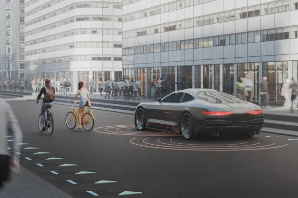
Electric vehicles (EVs) and internal combustion engine vehicles (ICEVs) use different powertrain components, but both powertrain architectures can be divided into an energy storage unit and a drive unit. EVs replace the fuel tank with a battery pack, which adds a battery management system (BMS). EVs also replace the engine with an electric motor, and a motor controller (MCU) replaces the engine control unit (ECU). In addition to these changes, EVs typically include a vehicle control unit (VCU). This article explains the role of the VCU in electric vehicles.
The vehicle control unit (VCU), also called the powertrain controller, is a core control component in new-energy vehicles. It must provide high reliability, good fault tolerance, electromagnetic compatibility, and environmental robustness to ensure safe and stable vehicle operation.
An analogy is useful: if the vehicle control system is like a student council, the VCU is the council president and other controllers are department heads. Just as the president assigns tasks, the VCU coordinates other control units so the vehicle can drive, brake, and steer.
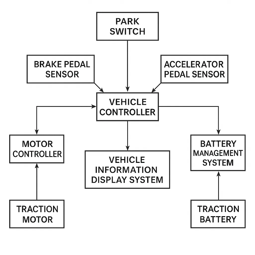
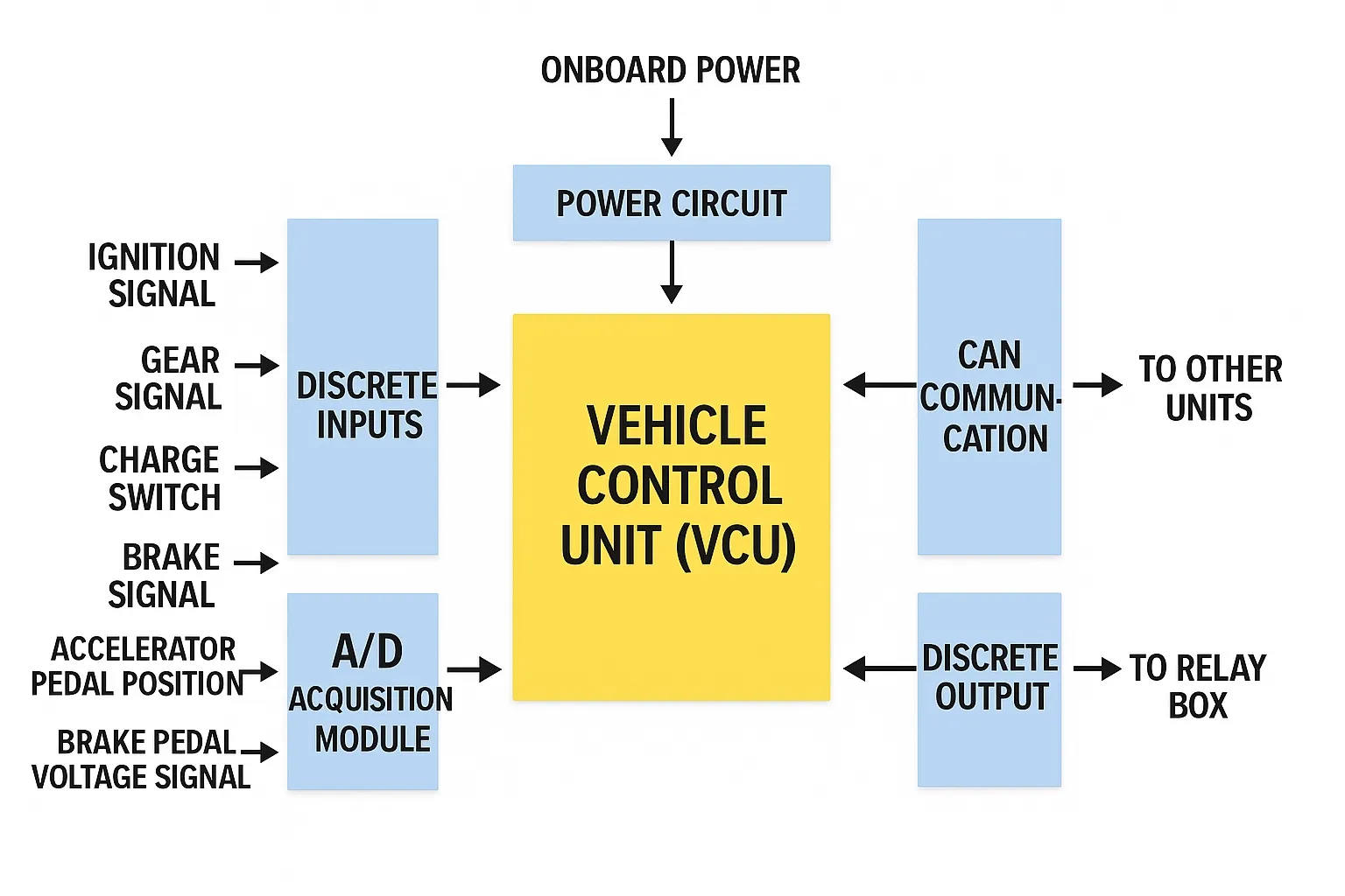
The VCU acquires accelerator pedal position signals, brake pedal signals, and other component signals, makes decisions based on these inputs, and controls lower-level actuators accordingly. The VCU also manages and schedules vehicle-wide operating status via the CAN bus.
02 Composition and Principles
Centralized and Distributed Architectures
Centralized control: the VCU independently acquires input signals, analyzes and processes data according to control strategies, and directly issues control commands to actuators to drive the EV.
Advantages of centralized control include consolidated processing, fast response, and lower cost. Disadvantages include more complex circuitry and greater thermal management challenges.
Distributed control: the VCU collects some driver signals and communicates with the motor controller and the battery management system over the CAN bus. The motor controller and the BMS forward their locally collected vehicle signals to the VCU over CAN. The VCU analyzes and processes vehicle information in combination with control strategies. After receiving control commands, the motor controller and the BMS use their current state information to control motor torque and battery discharge.
Advantages of distributed control include modularity and lower subsystem complexity. The disadvantage is relatively higher cost.
03 Core Functions
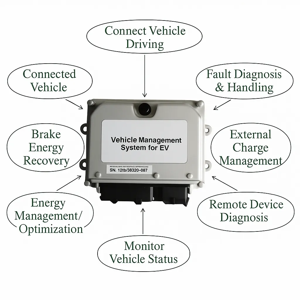
1. Vehicle drive control
The drive motor must produce driving or braking torque according to driver intent. When the driver presses the accelerator or brake pedal, the motor must supply driving power or regenerative braking power. Greater pedal opening corresponds to greater motor output. The VCU interprets driver inputs, receives feedback from vehicle subsystems, and issues control commands to achieve normal vehicle motion.
Related Reading: Selecting the Right Microcontroller for Your Autonomous Vehicle Control PCB
2. Vehicle network management
The VCU is one node among many controllers on the vehicle CAN bus. As the information-control center, the VCU organizes and transmits information, monitors network state, manages network nodes, and diagnoses and handles network faults.
3. Regenerative braking management
One key difference between EVs and ICEVs is the ability to recover braking energy by operating the motor in a generator mode. The VCU analyzes driver braking intent, battery pack state, and motor state, and applies regenerative braking control strategies. When conditions permit, the VCU issues motor mode and torque commands so the drive motor generates electricity and the recovered energy is stored in the battery without degrading braking performance.
4. Vehicle energy management and optimization
In EVs, the battery not only powers the drive motor but also supplies electrical accessories. To maximize driving range, the VCU manages vehicle energy use to improve efficiency. When battery state of charge (SOC) is low, the VCU can command certain accessories to limit output power to extend range.
5. Vehicle state monitoring and display
The VCU obtains real-time operating data by directly sampling signals and receiving CAN messages, including speed, motor mode, torque, rotational speed, remaining battery charge, pack voltage, cell voltages, battery temperature, and fault status. It transmits these real-time data to the vehicle information display via CAN. The VCU also periodically checks communication on the CAN bus; if a node fails to communicate, the VCU reports the fault to the display and takes appropriate emergency measures to prevent extreme conditions, allowing the driver to obtain accurate information about vehicle status.
Related Reading: Implementing CAN Bus Communication on an Autonomous Vehicle Control PCB
6. Fault diagnosis and handling
The VCU continuously monitors the vehicle electronic control system and performs fault diagnosis. Fault indicators and diagnostic trouble codes indicate the fault type and details. The VCU applies appropriate safety protections based on the fault. For less severe faults, the vehicle may be drivable at low speed to a nearby repair facility for service.
7. External charging management
The VCU controls charging connection, monitors the charging process, reports charging status, and manages charge termination.
8. Diagnostic tool interface and offline testing
The VCU connects to external diagnostic equipment and supports diagnostic communications and UDS services, including data stream reading, diagnostic trouble code read and clear, and control port debugging.