Introduction
The RA series development environment Flexible Software Package (FSP) provides a GUI-based peripheral configuration and generates driver code. When a peripheral needs to switch dynamically between functions (for example, UART <-> IRQ receive), some runtime changes must be made by modifying peripheral registers directly. The example below demonstrates a method that first configures the RXD pin as an IRQ to detect the start bit interval of incoming data, measures that interval to calculate the actual baud rate, and then reconfigures the UART baud rate dynamically. This enables automatic baud rate detection.
Example setup
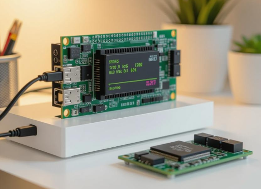
The demonstration uses the EK-RA2E1 evaluation board. UART1 (P401, P402) is configured as TXD1 and RXD1. On startup, the program switches the RXD1 pin to trigger IRQ4 on both falling and rising edges, then waits for the host PC to send a baud-rate identification byte (LSB = 1). Two IRQ4 events are used to start and stop a GPT timer, capturing the start bit interval and calculating the host's baud rate. After the calculation, IRQ4 is switched back to RXD and normal UART communication begins.
The EK-RA2E1 evaluation kit supports Renesas FSP and the e2 studio IDE for evaluation and firmware development. The board provides onboard features and optional ecosystem plugins for development work.
Configuration overview
- UART1 configuration
- GPT configuration
- Configure P402 pin as IRQ4
- Baud-rate calculation and related register configuration
- Switch P402 pin back to UART RXD
Notes
The method relies only on low-level register configuration to perform quick baud-rate detection, calculation, and reconfiguration. As long as the MCU system clock is within the required range, this approach can detect and configure nonstandard, very high, or very low baud rates.
 ALLPCB


