Introduction
During university I paid little attention to the internal memory structure and usage of microcontrollers. I only knew the basic difference between RAM and ROM and that a program stored in ROM could run. I did not understand how the startup process worked. After working in embedded systems for several months, I have developed some new understandings that I share here. Corrections and feedback are welcome.
RAM and ROM in Microcontrollers
Both ROM and RAM are semiconductor memories. ROM stands for read only memory and retains data when power is removed. RAM stands for random access memory and typically loses data on power loss; a typical example is a computer's main memory.
RAM is commonly categorized into two types: static RAM (SRAM) and dynamic RAM (DRAM). SRAM is very fast and is used where high-speed reads and writes are required, such as CPU caches. SRAM is expensive, so it is used only where necessary. DRAM holds data for a shorter time and is slower than SRAM, but it is faster than most ROM types and much cheaper than SRAM. General-purpose computer memory is usually DRAM.
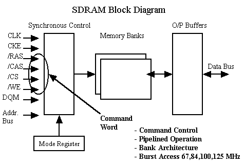
DRAM has many variants, including Fast Page, EDO, SDRAM, DDR, RDRAM, SGRAM and WRAM. Main memory is used to store data and code that are currently in use. The term "dynamic" in DRAM reflects the need to refresh stored data periodically because cells lose charge over time.
ROM also exists in several varieties. PROM is a programmable ROM written once; after programming it cannot be changed. EPROM (erasable programmable ROM) can be erased with ultraviolet light and reprogrammed. EEPROM can be electrically erased, but it is relatively expensive and write operations are slower.
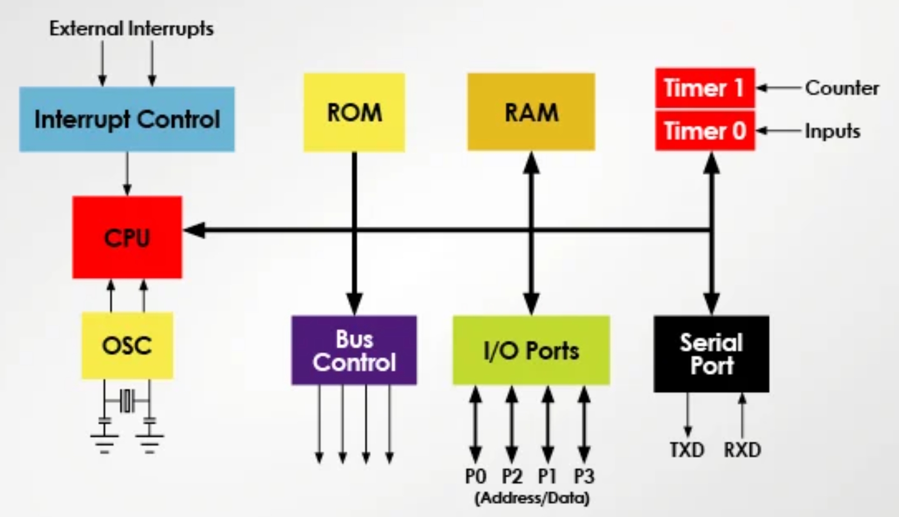
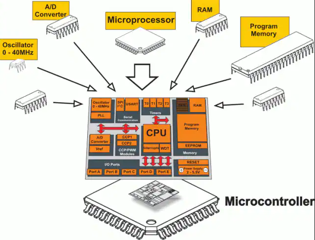
In simple microcontrollers such as the original AT89C51, on-chip ROM and RAM are provided. ROM stores compiled programs, constants and lookup tables; its contents persist across power cycles so the system resumes running after power-up. RAM stores temporary user variables and internal registers; its contents are lost on power loss, so software reinitializes registers and variables on startup.
MCS-51 Program Execution and Memory Organization
The MCS-51 family uses a Harvard architecture: program memory and data memory are completely separate and have independent addressing systems. On-chip and off-chip data memories each have their own address spaces, so addresses can overlap across these spaces. For example, address 0000H may exist in program memory, on-chip data memory, and off-chip data memory simultaneously.
A typical 89S51 has 4 kB of program memory from 0000H to 0FFFH. After reset, the program counter contains 0000H, so execution begins at 0000H. The code then jumps to the main routine; implementations may perform additional startup checks before calling main.
Flash in Embedded Systems
Many chips now use on-chip flash or external flash to store firmware. The main flash types are NOR flash and NAND flash.
NOR flash supports random access reads similar to SDRAM, allowing code to be executed directly from NOR flash. This can reduce the required SRAM size and lower system cost.
NAND flash does not support random byte reads; it reads and writes in blocks or pages (commonly 512 bytes per page). NAND flash provides higher density and lower cost, but code cannot be executed directly from NAND. Systems that use NAND flash often include a small NOR flash to hold startup code.
Small systems commonly use NOR flash for boot code and other critical data because of its fast random-read capability, while large-capacity storage typically uses NAND flash for its higher density and faster block erase/program performance. NAND usage requires flash management and special system interfaces.
Serial flash devices with SPI interfaces support page reads and arbitrary-address reads. They may offer quad-SPI or dual-SPI DDR interfaces. It is possible to execute code directly from external serial flash by using an external address bus over SPI, though execution speed is a consideration.
Embedded Boot Loader
Embedded systems use various startup methods depending on the chip architecture. In general computing, the boot process involves firmware (BIOS) and an OS boot loader located in the disk MBR. The BIOS is a small resident program that initializes hardware and loads the OS boot loader into RAM, which then loads the kernel into RAM and transfers control to it.
Many embedded CPUs include a small ROM with a fixed startup routine that loads a boot loader. Other CPUs start execution at a fixed address (for example 0x00000000) where a boot loader is located.
Boot loaders commonly operate in two modes: downloader mode and loader mode. Downloader mode is used during development: a debugger or programmer writes code into internal RAM and the boot loader then programs the target flash or storage. In production, the boot loader runs in loader mode. Its main tasks include hardware initialization, stack setup, memory mapping checks, and loading system images or program segments from flash into internal RAM or external SDRAM, or in some designs, executing directly from external flash.
 ALLPCB


