ALLPCB


Overview
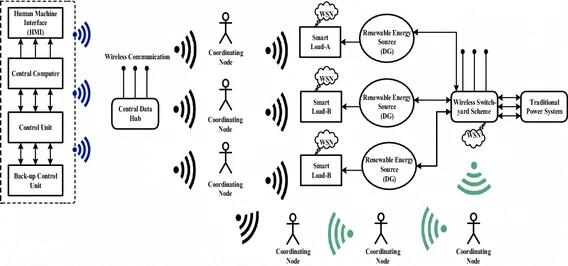
In recent years, PoE (power-over-Ethernet) technology has become increasingly prevalent. By simplifying device installation and deployment and providing energy-efficient and safer power delivery, PoE is widely used in wireless coverage, security surveillance, and smart grid applications. In technical discussions, a common area of confusion among integrators concerns PoE power delivery. This article summarizes the main questions and provides clear answers.
PoE Classification
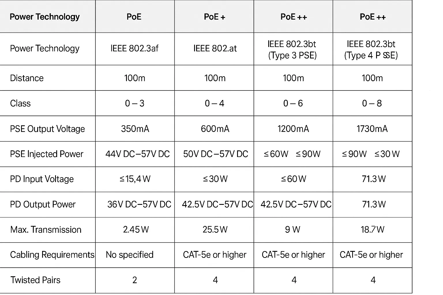
PoE devices are classified based on whether they conform to the IEEE standards published by the IEEE Standards Association: IEEE 802.3af, IEEE 802.3at, and IEEE 802.3bt. Devices are grouped into standard PoE and non-standard PoE.
Standard PoE: Devices that conform to the IEEE PoE standards (IEEE 802.3af, IEEE 802.3at, IEEE 802.3bt).
Non-standard PoE: Devices that do not conform to the IEEE PoE standards.
PoE Power System Components
PoE power supply: The PoE power supply provides power for the entire PoE system. The number of PDs (powered devices) supported by a PSE depends on the power capacity of the PoE power supply. PoE power supplies can be either internal or external units.
Power-sourcing Equipment (PSE): A PoE device that supplies power to PDs over Ethernet cabling and provides detection, classification, and power-management functions. PSE devices may be standard or non-standard depending on compliance with IEEE specifications (for example, standard PoE switches versus non-standard PoE switches).
Powered Device (PD): An IP terminal device that receives power from a PSE (for example, IP phones, wireless access points, network cameras). PDs may be standard or non-standard depending on IEEE compliance.
PoE Power Delivery Principle
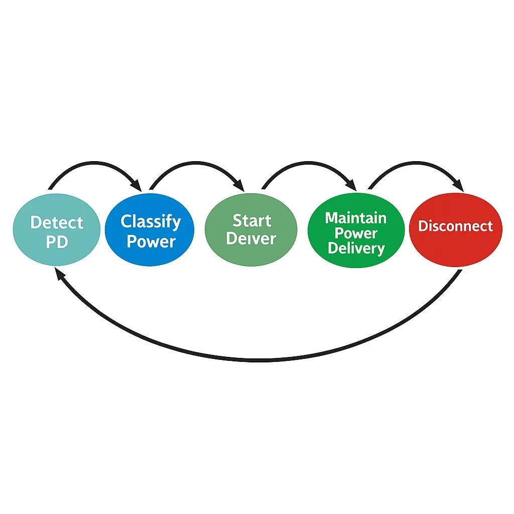
According to IEEE 802.3af, IEEE 802.3at, and IEEE 802.3bt, a PSE must detect and classify an attached network device within a defined time window before applying power, and then decide whether to provide power and how much. This prevents incompatible devices from being damaged by the applied 48 VDC. The PSE's primary functions are to detect whether a compatible PD is connected or disconnected, classify the PD's power level, and then enable or disable power accordingly.
PoE Wiring Pairs
For PoE (IEEE 802.3af) and PoE+ (IEEE 802.3at), power can be delivered using either two data pairs or two spare pairs in the cable. These two powering methods are known as Alternative A (data pairs) and Alternative B (spare pairs).
Alternative A: Data Pair Powering (pins 1/2 and 3/6)
Under Alternative A, the PSE injects DC power onto the data pairs (pins 1/2 and 3/6). Because the DC frequency does not interfere with the data signaling, the same pair can carry both data and power. The PSE connects to the PD through PoE transformers; power is supplied and received via the transformers' center taps. The following diagram illustrates data-pair powering.
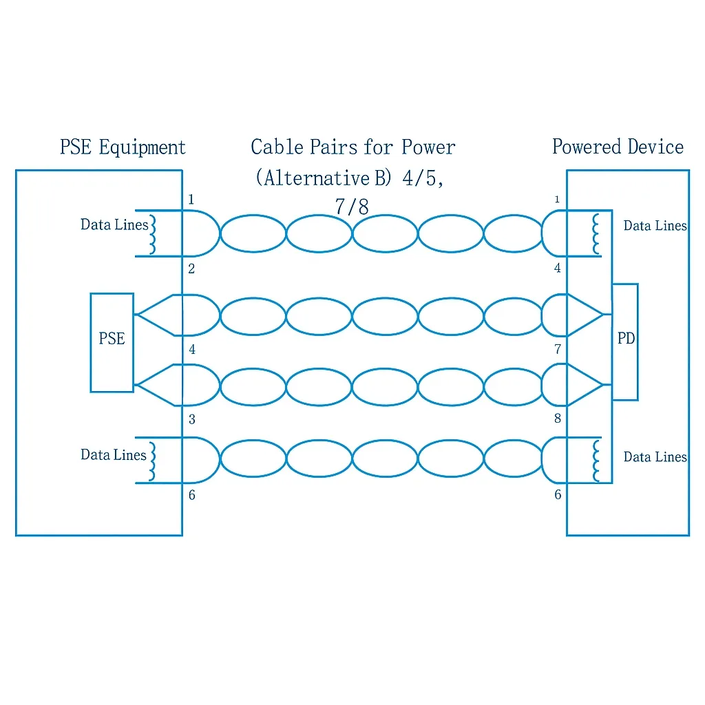
Alternative B: Spare Pair Powering (pins 4/5 and 7/8)
Under Alternative B, the PSE injects DC power onto the spare pairs (pins 4/5 and 7/8). The DC is injected so it coexists with data on the cable without interference. Power is supplied and received via PoE transformers center taps as in Alternative A. The following diagram illustrates spare-pair powering.
Summary of Alternative A and B
- Alternative A uses pairs 1/2 and 3/6 for power. One pair is positive and the other is negative according to the standard.
- Alternative B uses pairs 4/5 and 7/8 for power. One pair is positive and the other is negative according to the standard.
Because 100 Mbps Ethernet uses pairs 1/2 and 3/6 for data, while 1 Gbps Ethernet uses all four pairs (1/2, 3/6, 4/5, 7/8) for data, the following applies:
- For 100 Mbps PoE switches: Under Alternative A, only conductors 1, 2, 3, and 6 are required to be connected. Under Alternative B, an 8-conductor cable is required and all eight conductors must be connected.
- For 1 Gbps PoE switches: Due to data transmission requirements, all eight conductors must be connected regardless of Alternative A or B.
Note: A PSE only needs to support either Alternative A or Alternative B. A PD must support both Alternative A and Alternative B. The maximum standard PoE cable length is 100 meters. Currently, many PoE switches on the market use Alternative A.
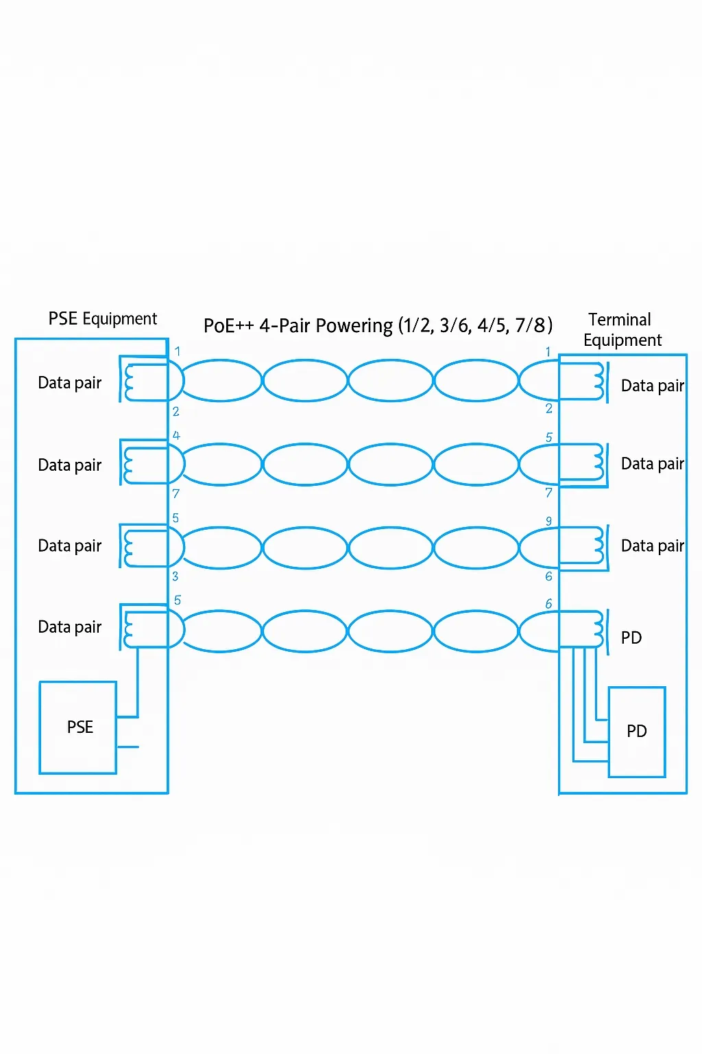
PoE++ (IEEE 802.3bt) Wiring
PoE++ (IEEE 802.3bt) uses all four pairs (1/2, 3/6, 4/5, 7/8) to supply power. The PSE injects DC on all four pairs and the PD receives power via the corresponding PoE transformer center taps. The following diagram illustrates four-pair powering.
Pair Polarity
The standard specifies the polarity for the positive and negative conductors in Alternative A, Alternative B, and the PoE++ four-pair scheme. The pair polarity illustration is shown below.