ALLPCB


Motors in electronic projects
When engineers design electronic projects, the primary goal is to implement the required functionality. Although project functions vary widely, many share a common actuator: the motor. For example:
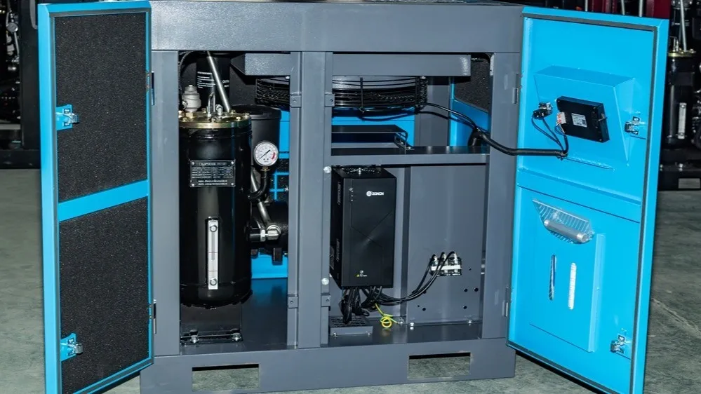
- An air purifier removes PM2.5 particles and relies on a motor-driven fan to circulate air.
- A paper shredder destroys discarded documents to prevent company secrets from leaking; a motor drives the rotating blades that shred the paper.
- A smart electric toy car implements reversing, forward motion, turning, and braking via remote control; a motor drives the wheels to follow the controller's commands.
Motors convert electrical energy into mechanical energy, acting as the link between the electronic circuit and the mechanical system. Circuit designers use basic electronic components and ICs, applying circuit laws to control voltages and currents. A complete product includes both electronic and mechanical parts, which is why electronic and mechanical engineers collaborate. Because motors bridge circuits and mechanics, effective motor control is a key part of many designs.
Motor categories and control approaches
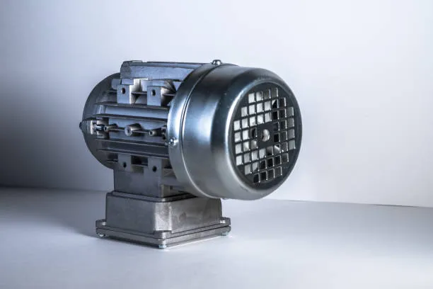
Motors are broadly classified by the type of current they use: AC motors and DC motors. This article focuses on DC motors to explain motor control in circuits. Common DC motor types include brushed DC motors, brushless DC motors, and stepper motors. A DC motor has two terminals: positive and negative. When the supply's positive and negative are applied to these terminals, a current path is formed and the motor rotates. The motor speed n is approximately n = (U - Ia*Ra) / (Ceφ); changing the applied voltage U is a simple way to adjust speed.
In circuit designs, engineers commonly choose between two approaches for driving DC motors: an H-bridge built from four MOSFETs, or a dedicated motor driver IC.
Option 1: MOSFET H-bridge
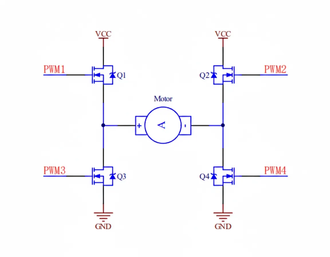
An H-bridge uses four MOSFETs arranged in an H shape, with the motor connected between the two bridge midpoints. The bridge can be implemented with four N-channel MOSFETs or with two N-channel and two P-channel MOSFETs. Typically, the high-side MOSFET drains (Q1 and Q2) connect to VCC and the low-side MOSFET sources (Q3 and Q4) connect to GND. The MOSFET gates are driven by external PWM signals PWM1, PWM2, PWM3, and PWM4.
For example, if PWM1 turns Q1 on and PWM4 turns Q4 on while PWM2 and PWM3 turn Q2 and Q3 off, the motor terminals see left-positive and right-negative, producing forward rotation. Reversing which MOSFETs are on swaps the terminal polarities and reverses rotation. Note that the MOSFET gate drive signals may come directly from a microcontroller or from an external gate driver IC.
Option 2: Dedicated motor driver IC
Integrated circuits can be specialized or general-purpose. A dedicated motor driver IC is a semiconductor designed specifically for motor drive applications and exposes a simpler external interface than a discrete H-bridge. The example below shows a typical application circuit.
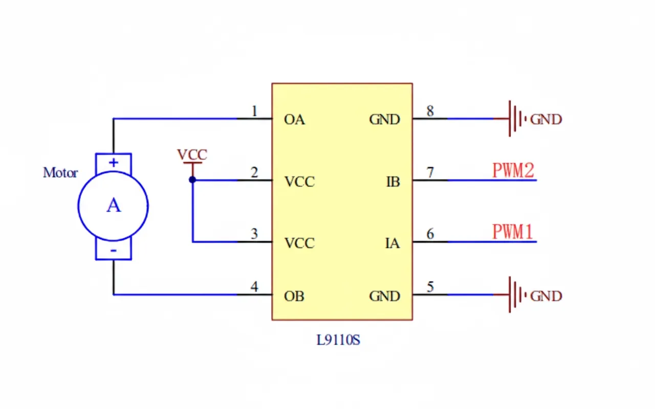
In the typical application, pins OA and OB connect directly to the motor terminals, input pins IA and IB accept PWM signals from a microcontroller, and VCC/GND connect to the power supply (decoupling capacitors omitted here). The PWM signals are provided directly by the microcontroller without additional driver chips in many cases.
Comparing discrete H-bridge and dedicated driver IC
Both approaches can drive motors, but they differ in three main aspects: circuit power, design difficulty, and stability/reliability.
1. Circuit power
Circuit power is P = U * I. The maximum voltage and current a MOSFET H-bridge can handle depend on the chosen MOSFETs. MOSFETs are available across a wide voltage range (for example, tens of volts up to several hundred volts or more) and a wide current range (from 1 A to hundreds of amps). A discrete MOSFET solution can therefore support high-power motor drives.
Dedicated motor driver ICs are limited by their supply voltage and current ratings. Typical IC supply voltages are 3.3 V, 5 V, 12 V, 24 V, and 36 V, and current ratings are often in the hundred-milliamp to single-digit-ampere range. Because integrated driver ICs have limited thermal dissipation capability, driving large voltages and currents can cause overheating and device failure.
Therefore, MOSFET H-bridge solutions generally support higher power than typical dedicated motor driver ICs.
2. Design difficulty
Design difficulty covers both circuit design and debugging. A discrete H-bridge requires managing four MOSFET gate signals and selecting and testing MOSFET parameters, which complicates both design and debugging. A dedicated motor driver IC reduces external component count and typically requires only two PWM control inputs, simplifying development and testing.
As a result, dedicated motor driver ICs generally reduce design difficulty compared with discrete MOSFET H-bridges.
3. Stability and reliability
Stability and reliability relate to immunity to external interference and overall robustness. In general, higher integration and fewer discrete components reduce the number of potential failure points and can improve reliability. A MOSFET H-bridge uses at least four discrete components, while a dedicated driver solution can consolidate functionality into a single IC.
Consequently, dedicated motor driver ICs often offer higher stability and reliability, making them better suited for harsh operating environments.
Conclusion
The key differences between MOSFET H-bridge solutions and dedicated motor driver ICs include circuit power, design difficulty, reliability, and also BOM component costs. Because each project has different requirements, the exact MOSFET or driver IC choice and the surrounding components will vary.
In general:
- For high-power motor applications, engineers often prefer a MOSFET H-bridge.
- When development and debugging resources or experience are limited, a dedicated motor driver IC is often simpler to implement.
- For applications in harsh environments where reliability is critical, dedicated motor driver ICs can provide higher stability.