 ALLPCB


When designing a printed circuit board (PCB), one of the critical aspects to consider is the drill size for non-plated through holes (NPTH). These holes, unlike their plated counterparts, do not have a conductive copper layer and are primarily used for mechanical purposes such as mounting or alignment. The minimum drill size for NPTH typically starts at around 0.2 mm (8 mils), but it can vary based on the PCB manufacturer’s capabilities, the board’s purpose, and the specific application. Factors like the size of screws, standoffs, or alignment pins often dictate a larger size, commonly ranging from 1.0 mm to 3.2 mm for mounting holes.
In this comprehensive guide, we’ll dive deep into the world of NPTH, exploring the ideal drill sizes, their applications, and essential design guidelines. Whether you’re an engineer working on a complex multi-layer board or a hobbyist creating a simple prototype, understanding NPTH specifications can save time, reduce costs, and ensure a reliable design. Let’s break down everything you need to know about PCB NPTH drill size, non-plated through hole size, drill size for mounting holes, mechanical PCB holes, and NPTH design guidelines.
What Are Non-Plated Through Holes (NPTH) in PCB Design?
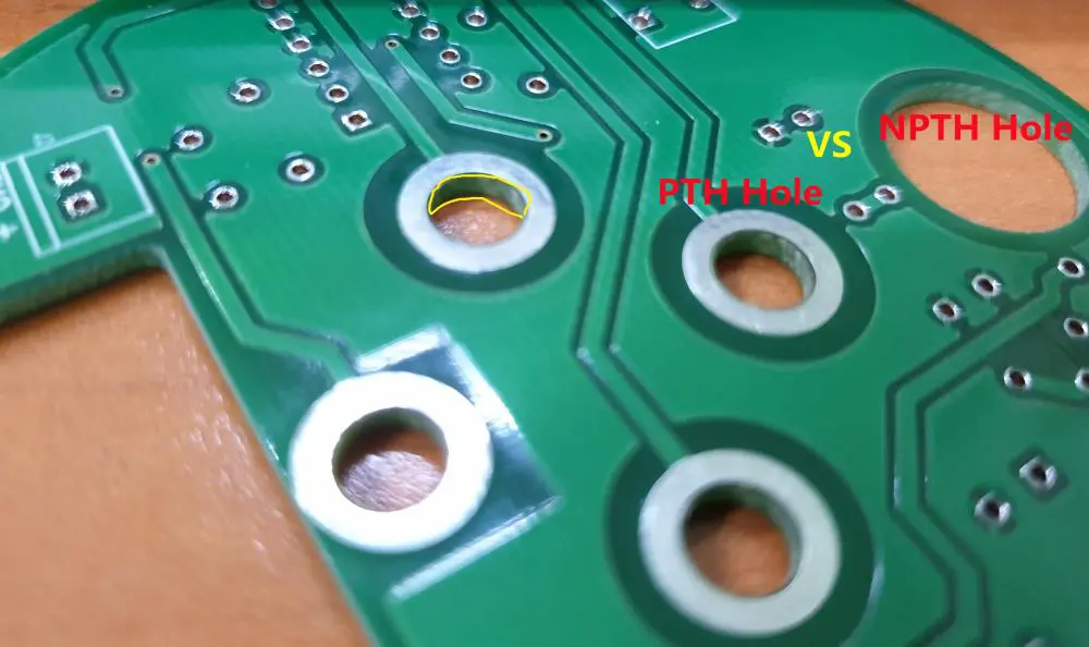
Non-plated through holes, or NPTH, are holes drilled through a PCB that do not have a conductive copper plating on their inner walls. Unlike plated through holes (PTH), which are used for electrical connections between layers or for mounting through-hole components, NPTH serves purely mechanical functions. These holes are essential for securing the PCB to an enclosure, aligning components, or providing clearance for screws and bolts.
The key difference between NPTH and PTH lies in their purpose and construction. Since NPTH lacks copper plating, it cannot conduct electricity and is not connected to any circuit traces. This makes them ideal for applications where electrical isolation is necessary or where the hole’s role is purely structural. Common examples include mounting holes for screws (often 2.5 mm to 3.5 mm in diameter) and alignment holes for assembly (sometimes as small as 1.0 mm).
Why Drill Size Matters for Non-Plated Through Holes
The drill size for NPTH directly impacts the functionality and manufacturability of a PCB. Choosing the right non-plated through hole size ensures that mechanical components fit properly, the board remains structurally sound, and manufacturing errors are minimized. Here are some reasons why drill size is critical:
- Fit and Compatibility: For mounting holes, the drill size must match the diameter of screws or fasteners. A hole that’s too small won’t accommodate the fastener, while one that’s too large can cause looseness or misalignment. For instance, an M3 screw typically requires a 3.2 mm drill size for a snug fit.
- Manufacturing Constraints: PCB fabrication houses have minimum drill size limits, often starting at 0.2 mm to 0.3 mm for NPTH. Smaller sizes may increase costs or risk drill bit breakage during production.
- Board Integrity: Oversized holes or improper spacing can weaken the PCB, especially in high-stress areas. Maintaining appropriate sizes and clearances is vital for durability.
Understanding the minimum drill size for NPTH and the intended application helps avoid costly redesigns and ensures the board meets both mechanical and manufacturing requirements.
Minimum Drill Size for NPTH: What You Need to Know
The minimum drill size for non-plated through holes typically depends on the capabilities of the PCB manufacturer and the specific tools used in the drilling process. Most standard fabrication processes support a minimum NPTH drill size of 0.2 mm (8 mils). However, for practical applications like mounting holes, the sizes are usually larger, ranging from 1.0 mm to over 3.0 mm, depending on the fastener or mechanical component used.
For smaller NPTH sizes below 0.3 mm, specialized drilling equipment or laser drilling may be required, which can increase production costs. Additionally, very small holes may not be suitable for mechanical purposes due to their fragility. Therefore, it’s common to see NPTH sizes for mounting or alignment starting at 1.0 mm or higher to ensure reliability.
Key Data Point: According to industry standards, the aspect ratio (hole depth to diameter) for NPTH should ideally not exceed 10:1 to avoid drilling issues. For a 1.6 mm thick PCB, this means the minimum drill size should be around 0.16 mm, though practical limits often push this to 0.2 mm or more.
Applications of Non-Plated Through Holes in PCB Design
Non-plated through holes are used in a variety of applications where mechanical support or isolation is needed. Here are some of the most common uses of NPTH in PCB design, along with typical drill sizes for each:
1. Mounting Holes for Mechanical Fastening
Mounting holes are the most frequent application of NPTH. These holes allow screws, bolts, or standoffs to secure the PCB to an enclosure or frame. The drill size for mounting holes depends on the fastener type:
- M2 Screws: Drill size of approximately 2.2 mm to 2.5 mm.
- M3 Screws: Drill size of 3.2 mm to 3.5 mm.
- M4 Screws: Drill size of 4.2 mm to 4.5 mm.
These sizes provide a slight clearance to ensure easy assembly while maintaining a secure fit. Engineers must also consider the placement of these holes to avoid interference with traces or components.
2. Alignment and Positioning Holes
Alignment holes are used to position the PCB during assembly or to align it with other boards or hardware. These holes are often smaller, with drill sizes ranging from 1.0 mm to 2.0 mm, depending on the pin or fixture used. Precision is key here, as even a slight mismatch can lead to assembly errors.
3. Clearance Holes for Isolation
In some designs, NPTH is used to create clearance around high-voltage areas or to isolate certain parts of the board. These holes prevent accidental contact or arcing and typically have larger diameters, often exceeding 3.0 mm, to ensure adequate spacing.
NPTH Design Guidelines for Optimal PCB Performance
To ensure that your PCB design is both functional and manufacturable, follow these NPTH design guidelines. These tips focus on drill size for mounting holes, spacing, and other critical factors for mechanical PCB holes.
1. Choose the Right Drill Size
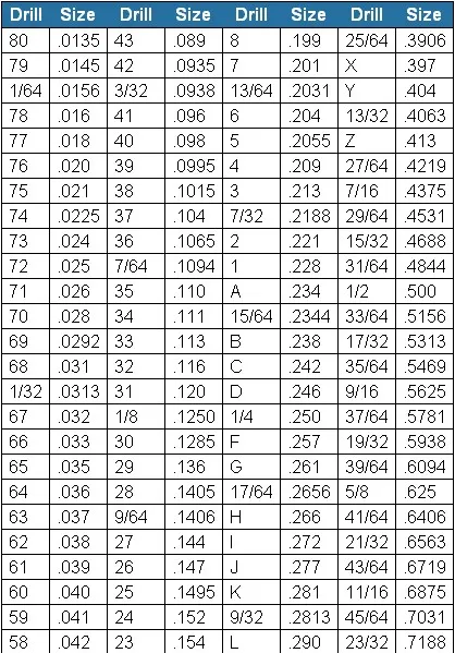
Select a drill size that matches the mechanical component or fastener. Refer to standard screw charts to determine the appropriate non-plated through hole size. For example, an M3 screw typically requires a 3.2 mm hole for a clearance fit. Avoid undersizing, as it can make assembly difficult, or oversizing, which can weaken the board.
2. Maintain Minimum Clearances
Ensure that NPTH holes are placed away from copper traces, pads, and other components to prevent damage or short circuits during drilling. A minimum clearance of 0.5 mm to 1.0 mm between the hole edge and any copper feature is generally recommended, though this can vary based on the board’s complexity and manufacturer guidelines.
3. Avoid Overlapping Board Edges
If an NPTH hole overlaps the board’s edge or contour, it may be treated as part of the outline rather than a hole. Clearly define such features in your design files to avoid confusion during manufacturing. For holes near the edge, maintain at least 0.3 mm of material between the hole and the board outline to prevent structural issues.
4. Specify NPTH in Design Files
Clearly mark NPTH holes in your PCB design software and include them in the drill file. Indicate that these holes should not have copper plating to avoid manufacturing errors. Most design tools allow you to specify NPTH by assigning them to a mechanical layer or labeling them separately from PTH holes.
5. Check Manufacturer Capabilities
Different PCB fabrication services have varying minimum drill sizes and tolerances for NPTH. Standard capabilities often support drill sizes down to 0.2 mm, but for smaller sizes or tighter tolerances (e.g., ±0.05 mm), confirm with the manufacturer beforehand. Specialized drilling may be needed, which can affect lead times and costs.
Common Challenges with NPTH Drill Sizes and How to Avoid Them
Designing with NPTH can present challenges, especially if drill sizes or placements are not carefully considered. Here are some common issues and solutions:
- Drill Breakage: Using a drill size below the manufacturer’s minimum (e.g., under 0.2 mm) can lead to broken drill bits and production delays. Always verify the minimum supported size and opt for slightly larger holes if possible.
- Misalignment: Incorrect drill sizes for alignment holes can cause assembly issues. Double-check the dimensions of pins or fixtures and test-fit where feasible.
- Structural Weakness: Placing large NPTH holes too close together or near the board edge can compromise the PCB’s strength. Use simulation tools or consult with your manufacturer to ensure the design withstands mechanical stress.
How to Specify NPTH Drill Sizes in Your PCB Order
When submitting a PCB design for manufacturing, clarity is essential to ensure that NPTH holes are drilled correctly. Follow these steps to specify drill sizes and avoid errors:
- Include a detailed drill file (often in NC or Excellon format) with your design package. This file should list all hole sizes and indicate which are NPTH.
- Provide a fabrication drawing or note specifying that certain holes are non-plated. This prevents accidental plating of mechanical holes.
- Communicate any special requirements, such as tight tolerances (e.g., ±0.1 mm), to the manufacturer during the quoting process.
By providing clear documentation, you reduce the risk of miscommunication and ensure that the PCB meets your mechanical and functional needs.
Conclusion: Mastering NPTH Drill Sizes for Better PCB Designs
Non-plated through holes play a vital role in PCB design, providing essential mechanical support through mounting holes, alignment features, and clearance spaces. Understanding the minimum drill size for NPTH—typically starting at 0.2 mm but often larger for practical applications like 3.2 mm for M3 screws—helps ensure a reliable and manufacturable design. By following NPTH design guidelines, such as maintaining clearances, choosing appropriate drill sizes for mounting holes, and verifying manufacturer capabilities, you can avoid common pitfalls and create robust mechanical PCB holes.
Whether you’re designing for a small prototype or a large-scale production run, paying attention to PCB NPTH drill size and non-plated through hole size is crucial. With the right approach, you can achieve a balance between functionality, durability, and cost-effectiveness in your PCB projects. Keep these tips in mind, and you’ll be well on your way to mastering the art of NPTH design.


