 ALLPCB


Overview
Wearable devices can change health and medical monitoring. Heart rate provides important insight into cardiac function during activity and rest. Innovations in optical semiconductor and low-power integrated circuits have enabled the transition to wearable devices. Historically, advanced products were offered mainly by organizations with large development budgets.
The Maxim MAXREFDES117 reference design provides a wearable sensor platform for developers. The design measures heart rate and pulse oxygen saturation (SpO2) using the MAX30102, which integrates red and infrared LEDs for heart rate and SpO2 detection. The small board size, 12.7 mm x 12.7 mm (0.5 in x 0.5 in), is suitable for wearable applications and can be sewn into fabric for rapid prototyping. Example firmware is available for Arduino and mbed platforms. The user must supply a 2 V to 5.5 V power source capable of providing 1.5 mA (typical at 3.3 V input); this is compatible with most batteries and Arduino or mbed form-factor boards.
Design Summary
The MAXREFDES117 design includes a PPG-based heart rate and SpO2 sensor subsystem. Key components are the MAX30102 heart-rate/SpO2 sensor (with integrated red and infrared LEDs), a low-power step-down regulator MAX1921, and a precision level translator MAX14595. With the example firmware, the complete design typically operates below 5.5 mW. The system block diagram is shown in Figure 1.
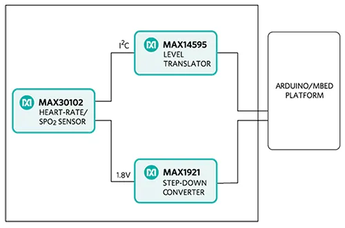
Figure 1: MAXREFDES117 reference design block diagram.
Note: the controller board is powered separately.
The MAXREFDES117 reference design is a PPG-based heart rate and SpO2 monitoring subsystem. The circuit uses the MAX30102 sensor with integrated red and infrared LEDs. The MAX1921 step-down converter accepts 2 V to 5.5 V input and generates the 1.8 V rail required by the sensor. The MAX14595 level translator provides the interface between the sensor and a controller board that typically operates at different logic levels.
Firmware and Supported Platforms
The MAXREFDES117 can be used with almost any microcontroller that has an I2C interface. Example firmware for Arduino and mbed has been tested on these development platforms:
- mbed: Maxim Integrated MAX32600MBED, NXP FRDM-K64F, NXP FRDM-KL25Z
- Arduino: Adafruit Flora, SparkFun Lilypad USB, Arduino UNO
Users can read sampled data via a terminal program, compute heart rate and SpO2, and analyze results with tools such as Excel. The firmware flow is shown in Figure 2.
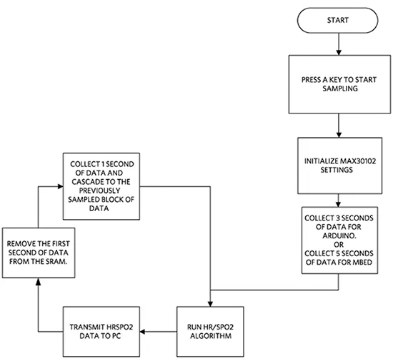
Figure 2: MAXREFDES117 firmware flowchart.
Full source code, including heart-rate and SpO2 algorithms, is provided to accelerate development. Code documentation is available in the corresponding firmware platform files (Arduino Platform or mbed Platform).
Heart-rate accuracy depends on the chosen platform. Tested mbed platforms provide more accurate heart-rate and SpO2 calculations than tested Arduino platforms because the mbed controllers have more RAM. For the example firmware, the mbed platform stores 5 seconds of samples collected at 100 sps, while the Arduino platform stores 4 seconds of samples collected at 25 sps.
SpO2 calculation is based on a polynomial relation in the ratio of infrared and red LED readings. The equation is:
SpO2 = C1 × AverageRatio^2 + C2 × AverageRatio + C3
where AverageRatio is the averaged ratio of IR to red LED readings, and C1, C2, and C3 are constants. Determining the constants requires comprehensive clinical data from a statistically significant population for this hardware. Such clinical testing is beyond the scope of this design; therefore, computed SpO2 values may contain error.
mbed Quick Start
Required items:
- Windows PC with USB port
- MAXREFDES117 board
- Five wires to connect MAXREFDES117 to the controller board
- One of the supported controller boards: Maxim Integrated MAX32600MBED, NXP FRDM-KL25Z, or NXP FRDM-K64F
- micro USB cable (for MAX32600MBED and FRDM-K64F)
- mini USB cable (for FRDM-KL25Z)
Procedure:
- Create an account on the mbed online compiler at developer.mbed.org.
- Import the demonstration program from the RD117_MBED project on the mbed site: https://developer.mbed.org/te.../Maxim-Integrated/code/RD117_MBED/
- Connect MAXREFDES117 to the controller board using the appropriate pin mapping:
MAX32600MBED port - MAXREFDES117 port P26 SDA - SDA P27 SCL - SCL P20 RX - INT 3.3V VIN - 3.3V VIN GND - GND FRDM-K64F port - MAXREFDES117 port E25 SDA - SDA E24 SCL - SCL D1 INT - INT P3V3 VIN - 3.3V VIN GND - GND FRDM-KL25Z port - MAXREFDES117 port E0 SDA - SDA E1 SCL - SCL D1 INT - INT 3.3V VIN - 3.3V VIN GND - GND
- Use a USB cable to connect the controller board to the PC.
- In the mbed compiler, select the appropriate controller board.
- Compile and download the generated binary to the mbed platform.
- Open HyperTerminal or a similar terminal program on the PC. Configure the correct COM port for 115200, 8-N-1 with no flow control.
- Place a finger on the top of U1 on the MAXREFDES117; touching the earlobe also works. Apply steady pressure for best results.
- Press any key in the terminal program to start conversions.
From left to right, the first two columns show red and infrared receiver data. The third and fifth columns show computed heart rate and SpO2 values. The fourth and sixth columns show the validity of the heart-rate and SpO2 calculations.
Arduino Quick Start
Required items:
- Windows PC with USB port
- MAXREFDES117 board
- Five-wire cable with alligator clips
- One of the supported controller boards: Adafruit Flora, SparkFun Lilypad USB, or Arduino UNO
- micro USB cable (for Lilypad or Flora)
- A-to-B USB cable (for Arduino UNO)
Procedure:
- If Arduino IDE is not installed on the PC, install it following the Arduino getting started guide.
- If using the Adafruit Flora board, install the Adafruit Windows drivers and set up Arduino IDE support for the Flora board following Adafruit's setup guide.
- Download the RD117_ARDUINO.zip source and extract it.
- Open RD117_ARDUINO.ino in Arduino IDE.
- Connect MAXREFDES117 to the controller board using the appropriate pin mapping:
Flora port - MAXREFDES117 port SDA - SDA SCL - SCL D10 - INT 3.3V VIN - 3.3V VIN GND - GND Lilypad USB port - MAXREFDES117 port 2 SDA - SDA 3 SCL - SCL 10 INT - INT + VIN - 3.3V VIN - GND - GND Arduino UNO port - MAXREFDES117 port SDA - SDA SCL - SCL 10 - INT 3.3V VIN - 3.3V VIN GND - GND
- Use a USB cable to connect the controller board to the PC.
- In Arduino IDE, select the appropriate board under the Tools menu.
- Select the correct COM port under the Tools menu.
- Upload the sketch using the Upload command in the Sketch menu.
- Open HyperTerminal or a similar terminal program on the PC. Configure the correct COM port for 115200, 8-N-1 with no flow control.
- Place a finger on the top of U1 on the MAXREFDES117; touching the earlobe also works. Apply steady pressure for best results.
- Press any key in the terminal program to start conversions.
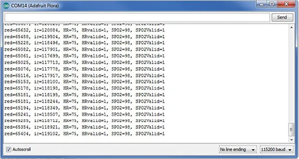
Figure 3: Example output from the MAXREFDES117. From left to right, the first two columns show red and infrared receiver data. The third and fifth columns show computed heart rate and SpO2 values. The fourth and sixth columns show the validity of the calculations.
Laboratory Measurements
Equipment used:
- MAX32600MBED
- Adafruit Flora
- Adafruit BlueFruit
- Polar H7 Bluetooth Smart heart-rate sensor
- Android tablet
Figures 4 and 5 show how MAXREFDES117 compares to the Polar H7 chest strap. Figure 4 shows data collected while seated for 20 minutes. Figure 5 shows data collected while walking at a normal pace for 20 minutes.
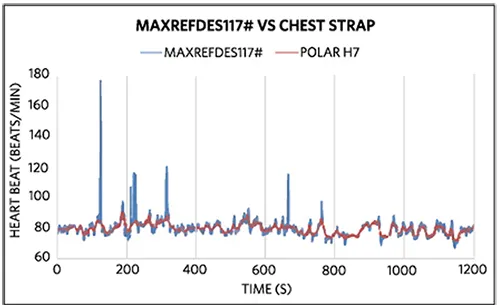
Figure 4: In the seated test, over 99% of mbed + MAXREFDES117 heart-rate data were within 5 beats per minute of the Polar H7 chest strap.
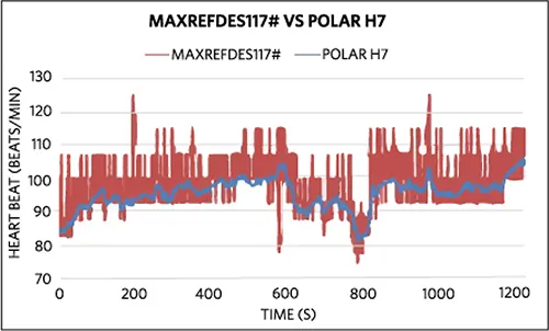
Figure 5: In the walking test, over 92% of Arduino + MAXREFDES117 heart-rate data were within 10 beats per minute of the Polar H7 chest strap.


