 ALLPCB


If you're new to PCB design, understanding the essential electronic components is the first step to creating functional and efficient circuit boards. This beginner's handbook will cover the common electronic components for PCB design, including resistors, capacitors, and inductors, along with placement tips, a guide to through-hole vs. SMD components, and advice on choosing the right parts for your project. Whether you're a hobbyist or an aspiring engineer, this guide will break down the basics and help you build a strong foundation for your PCB journey.
Let’s dive into the world of PCB design with a detailed exploration of components, their roles, and best practices for using them effectively.
What Are Electronic Components in PCB Design?
Electronic components are the building blocks of any printed circuit board (PCB). They are the individual parts that work together to control, store, or transform electrical energy within a circuit. These components are soldered or mounted onto the PCB to create a complete electronic system, such as a power supply, sensor, or microcontroller unit.
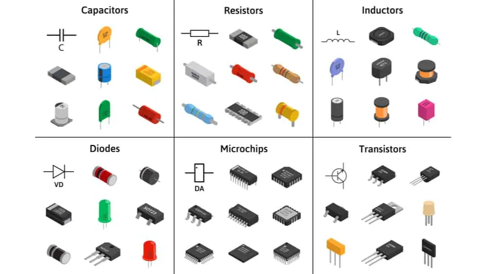
For beginners, it’s important to start with the most common electronic components for PCB design. These include passive components like resistors, capacitors, and inductors, as well as active components like diodes, transistors, and integrated circuits (ICs). Each component has a specific function, and knowing how to select and place them is key to a successful design.
Why Understanding Components Matters
Choosing the right components and placing them correctly on a PCB affects the performance, reliability, and cost of your project. Poor component selection can lead to signal interference, overheating, or even circuit failure. By learning the basics of electronic components for PCB design, you can avoid common pitfalls and build boards that work as intended.
Common Electronic Components for PCB Design
Let’s explore the most frequently used components in PCB design, their functions, and why they are essential for your projects.
1. Resistors
Resistors are passive components that limit the flow of electric current in a circuit. They are measured in ohms (Ω) and are often used to protect sensitive components by reducing voltage or current to safe levels. For example, a resistor might be used in series with an LED to prevent it from burning out by limiting current to 20mA.
Resistors come in various types, including carbon film and metal film, with power ratings from 1/8 watt to several watts. They are identified by color bands that indicate their resistance value and tolerance (e.g., a 1kΩ resistor with a 5% tolerance).
Related Reading: SMD Resistors Demystified: Sizes, Markings, and Practical Applications
2. Capacitors
Capacitors store and release electrical energy, acting like tiny batteries in a circuit. They are measured in farads (F), though most PCB capacitors are in the range of picofarads (pF) to microfarads (μF). Capacitors are used for filtering noise, smoothing voltage in power supplies, or timing in oscillator circuits. For instance, a 10μF capacitor might be placed near a microcontroller to stabilize power delivery.
There are different types of capacitors, such as ceramic, electrolytic, and tantalum, each suited for specific applications based on capacitance and voltage ratings.
3. Inductors
Inductors store energy in a magnetic field when current flows through them. Measured in henries (H), they are often used in power supply circuits to filter out high-frequency noise or in radio frequency (RF) designs. A typical inductor in a PCB might have a value of 10mH and be used to smooth out current fluctuations.
Inductors are less common in beginner projects but are vital for designs involving power conversion or signal processing.
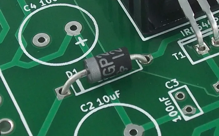
4. Diodes
Diodes are active components that allow current to flow in one direction only. They are essential for protecting circuits from reverse polarity or converting alternating current (AC) to direct current (DC) in rectifier circuits. A common diode like the 1N4007 can handle up to 1A of current and 1000V of reverse voltage.
Special types like Zener diodes are used for voltage regulation, while light-emitting diodes (LEDs) serve as indicators or light sources.
5. Transistors
Transistors act as switches or amplifiers in a circuit. They are fundamental to modern electronics, enabling logic operations in digital circuits or amplifying signals in analog designs. A popular transistor like the 2N2222 can handle currents up to 800mA and is often used in low-power switching applications.
There are two main types: bipolar junction transistors (BJTs) and field-effect transistors (FETs), each with unique characteristics.
6. Integrated Circuits (ICs)
Integrated circuits are complex components that combine thousands or millions of tiny transistors, resistors, and capacitors into a single chip. ICs, like microcontrollers or operational amplifiers, are the brains of most electronic devices. For example, the ATmega328P IC powers many beginner-friendly microcontroller boards with a clock speed of up to 20MHz.
ICs come in various packages, such as DIP (dual in-line package) for through-hole mounting or QFP (quad flat package) for surface mounting.
Resistor, Capacitor, Inductor PCB Placement Tips
Proper placement of components like resistors, capacitors, and inductors on a PCB is just as important as choosing the right ones. Poor placement can lead to signal interference, heat buildup, or manufacturing issues. Here are some beginner-friendly tips for effective resistor, capacitor, and inductor PCB placement.
General Placement Guidelines
- Group Related Components: Place components that work together, like a resistor and capacitor in a filter circuit, close to each other to minimize trace length and reduce noise. For example, keep a decoupling capacitor (e.g., 0.1μF) within 2-3mm of an IC’s power pin.
- Avoid Overcrowding: Leave enough space between components to prevent heat buildup and ensure easy soldering. A minimum spacing of 0.5mm between small components is a good rule of thumb.
- Orient for Readability: Align components like resistors and capacitors in the same direction for a neat layout and easier debugging.
Specific Tips for Resistors, Capacitors, and Inductors
- Resistors: Place resistors close to the components they protect or bias. For high-power resistors (e.g., 1W or more), ensure they are away from heat-sensitive parts to avoid thermal damage.
- Capacitors: Position decoupling capacitors near IC power pins to filter noise effectively. For electrolytic capacitors, ensure proper polarity alignment to prevent circuit failure.
- Inductors: Keep inductors away from sensitive signal traces, as their magnetic fields can cause interference. Place them near power input areas for filtering applications.
Through-Hole vs. SMD Components Guide
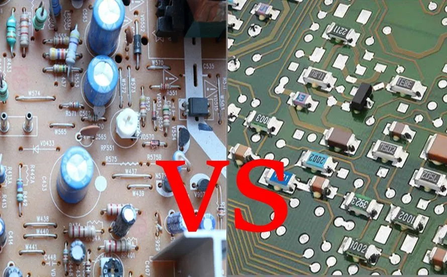
When designing a PCB, you’ll need to decide between through-hole and surface-mount device (SMD) components. Both have their advantages and challenges, especially for beginners. Let’s break down the differences in this through-hole vs. SMD components guide.
Through-Hole Components
Through-hole components have leads that pass through holes in the PCB and are soldered on the opposite side. They are larger and easier to handle, making them ideal for beginners.
- Pros: Easy to solder by hand, durable mechanical connections, suitable for high-power applications (e.g., a 5W resistor).
- Cons: Takes up more space, not ideal for compact or high-density designs, slower assembly for mass production.
- Best For: Prototyping, educational projects, and designs where size isn’t a constraint.
SMD Components
SMD components are mounted directly onto the surface of the PCB without leads passing through. They are smaller and used in most modern electronics.
- Pros: Compact size allows for smaller PCBs, better for high-speed signals (e.g., reduced parasitic inductance), supports automated assembly.
- Cons: Harder to solder by hand, requires precise placement, less durable under mechanical stress.
- Best For: Compact designs, mass production, and high-frequency applications.
Choosing Between Through-Hole and SMD
For beginners, start with through-hole components to learn soldering and circuit building. As you gain confidence, transition to SMD components for more advanced, compact designs. Many hobbyist projects use a mix of both, with through-hole for larger parts like connectors and SMD for ICs and passives.
Related Reading: The Ultimate Guide to Selecting the Right Connectors for Your PCB Components
Choosing Components for PCB Design: Key Factors
Selecting the right components for your PCB design can be overwhelming with so many options available. Here are some key factors to consider when choosing components for PCB design to ensure functionality and reliability.
1. Electrical Specifications
Match the component’s specifications to your circuit’s requirements. For example:
- Voltage Rating: Ensure a capacitor’s voltage rating (e.g., 25V) exceeds the circuit’s operating voltage (e.g., 12V) by at least 20-30% for safety.
- Current Rating: Choose a diode or transistor that can handle the expected current, like a diode rated for 2A for a 1.5A load.
- Power Dissipation: Select resistors with a power rating (e.g., 0.25W) higher than the calculated dissipation to avoid overheating.
2. Size and Package Type
Consider the physical size and mounting style (through-hole or SMD) based on your PCB layout and assembly method. Smaller SMD packages like 0402 (1.0mm x 0.5mm) save space but are harder to handle than larger 1206 packages.
3. Availability and Cost
Opt for components that are widely available and within your budget. Using standard values (e.g., a 10kΩ resistor instead of an obscure 9.7kΩ) ensures easier sourcing and lower costs.
4. Environmental Factors
If your PCB will operate in harsh conditions, choose components with appropriate temperature ranges (e.g., -40°C to 85°C for industrial use) or moisture resistance.
5. Manufacturer Reliability
Source components from reputable suppliers to avoid counterfeit or low-quality parts that could fail prematurely.
Electronic Component Basics for PCB: Best Practices
Now that you know the common components and how to choose them, let’s cover some best practices for working with electronic component basics for PCB design.
Start with a Schematic
Before placing components on a PCB, create a schematic diagram. This is a blueprint of your circuit showing how components connect. Use software tools to design and simulate your schematic to catch errors early.
Double-Check Polarity
Components like capacitors, diodes, and ICs have polarity. Incorrect placement (e.g., reversing an electrolytic capacitor) can damage the component or the entire circuit. Always verify markings and datasheets.
Use Datasheets
Datasheets provide critical information like pin configurations, electrical limits, and recommended usage. For example, an IC datasheet might specify a maximum input voltage of 5.5V, helping you avoid overvoltage conditions.
Test on a Breadboard First
For beginners, prototype your circuit on a breadboard before committing to a PCB layout. This allows you to test connections and component behavior without soldering.
Keep Learning
PCB design is a skill that improves with practice. Study basic circuits, experiment with small projects, and learn from each design to build your expertise over time.
Conclusion: Building Your PCB Design Skills
Mastering the essentials of electronic components for PCB design is a crucial step for any beginner. By understanding common components like resistors, capacitors, and inductors, learning effective placement strategies, and knowing how to choose between through-hole and SMD parts, you’re well on your way to creating functional and reliable circuit boards.
Start small with simple projects, use the tips and best practices outlined in this guide, and gradually take on more complex designs. With patience and practice, you’ll gain the confidence to tackle any PCB project. Remember, every expert was once a beginner, and the journey of learning electronic component basics for PCB design is both rewarding and exciting.
At ALLPCB, we’re committed to supporting your PCB design journey with resources and expertise. Dive into your next project with these fundamentals in mind, and watch your ideas come to life on a circuit board.


