ALLPCB


From this section, we analyze individual components used in EMC, including inductors, capacitors, ferrite beads, resistors, and ferrite cores. The primary focus here is capacitors.
1. Frequency is the key parameter
In EMC design, component characteristics are closely tied to frequency. Without considering frequency, discussing capacitors, inductors, or ferrite beads is meaningless.
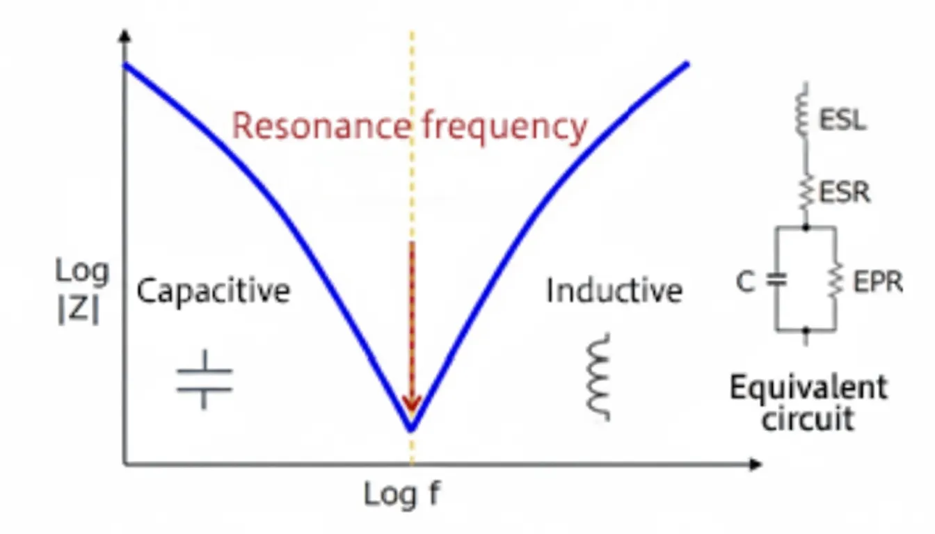
A capacitor can be modeled as a series combination of parasitic inductance and capacitance. When the operating frequency exceeds the self-resonant frequency, the capacitive reactance becomes smaller than the inductive reactance and the component starts to behave inductively. The self-resonant frequency can be estimated as:
f = 1/(2*pi*sqrt(C*ESL))
Because of this impedance behavior, choose capacitors based on their impedance over the relevant frequency range.
2. Capacitor vs. Inductor for EMI control
If inductors mainly reduce di/dt to improve EMC performance, capacitors reduce du/dt. The following example, from a DC-DC power stage, shows how adding capacitance at the output reduces the noise amplitude:
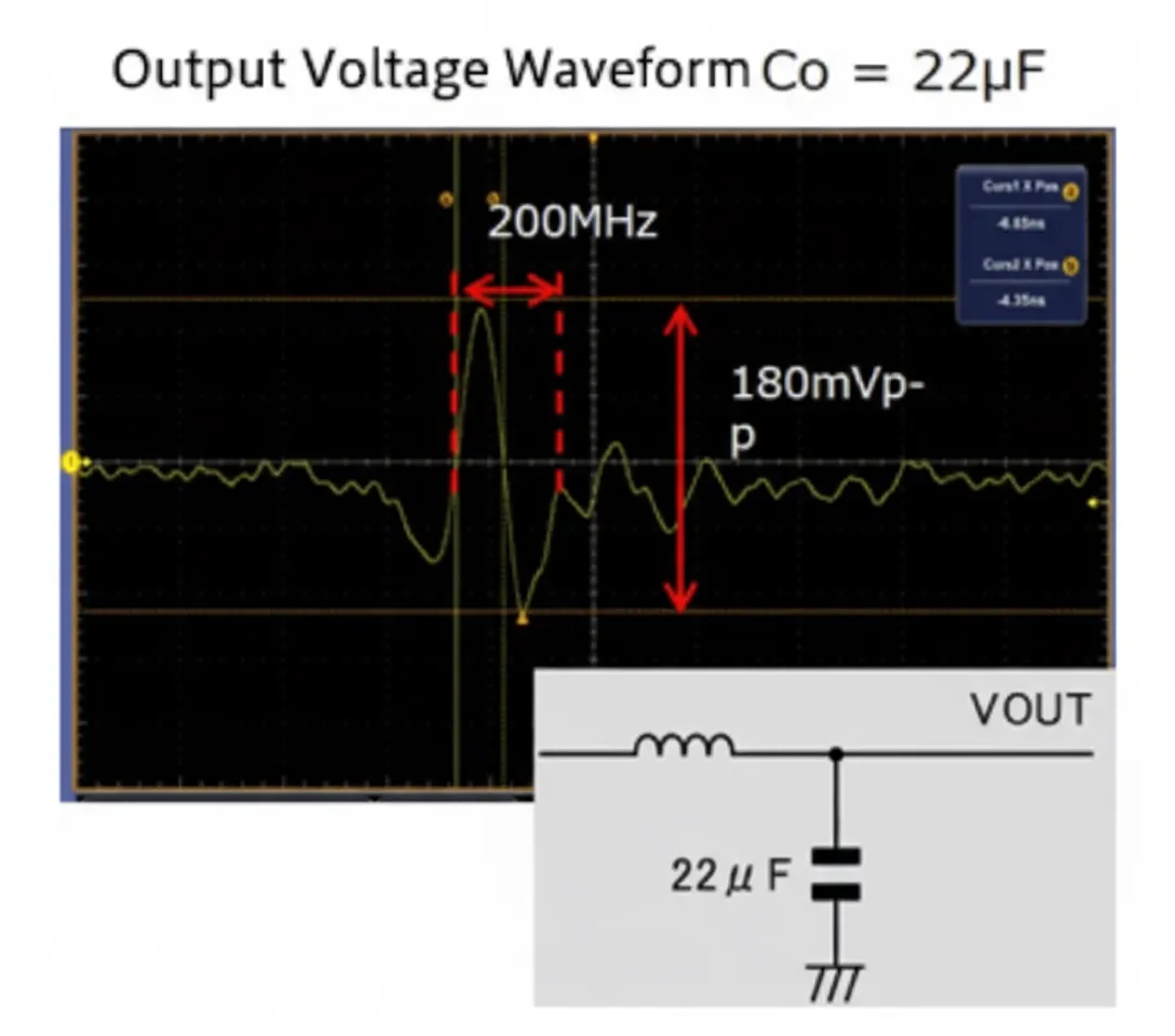
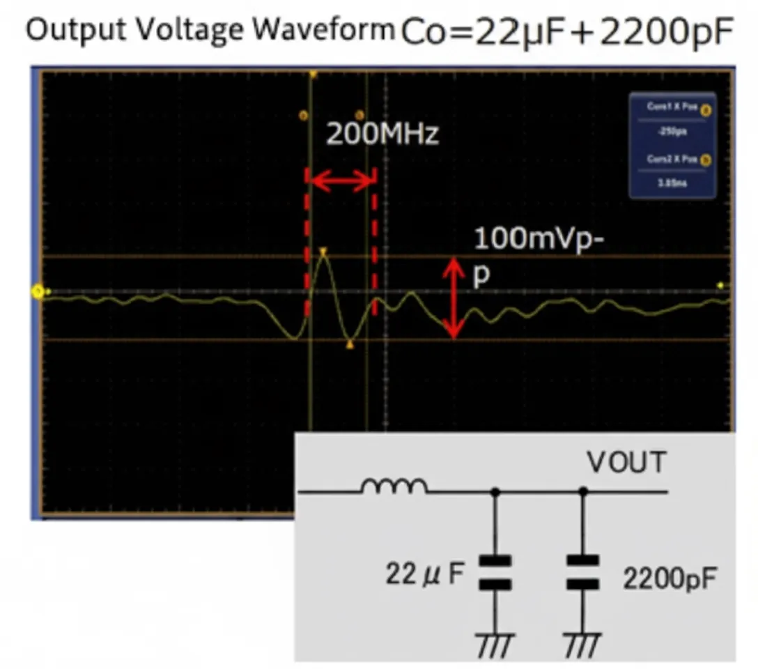
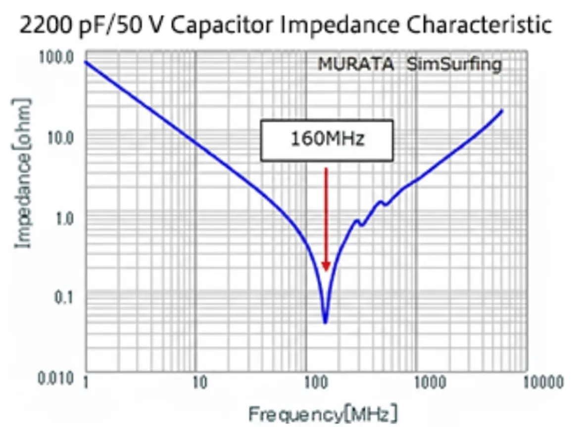
For example, adding a 2200 pF capacitor at the output (with self-resonant frequency around 100 MHz to 200 MHz) reduced the 200 MHz peak-to-peak noise from 180 mV to 100 mV. Since capacitive coupling voltage is proportional to j*w*U*C*R, reducing U reduces capacitive coupling.
This approach lowers the impedance at the target noise frequency and thereby reduces the noise amplitude. It is essential to know the signal frequency to select an appropriate capacitor, and to consult manufacturers' impedance curves because capacitor characteristics vary between vendors.
3. Practical rules for decoupling capacitors
Beyond selecting capacitors for target frequencies, consider the following:
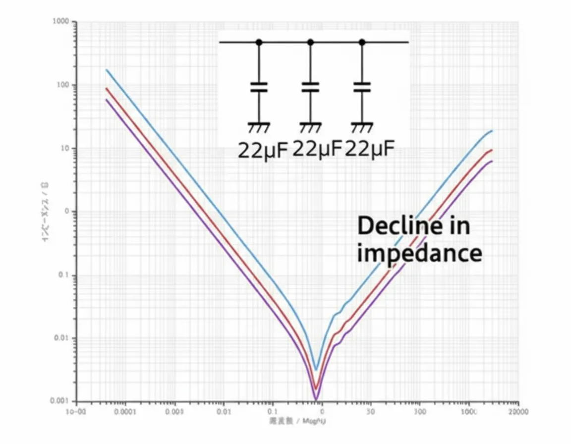
Parallel identical-value capacitors
Paralleling multiple capacitors of the same value can further reduce the amplitude at that frequency.
Parallel capacitors of different values
To address noise across multiple frequencies, place capacitors of different values in parallel. This can introduce anti-resonance points, however.
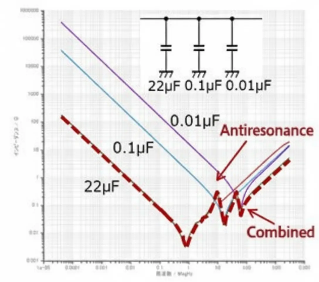
For example, a 22 μF capacitor may behave inductively above its self-resonant frequency. In combination with a 0.1 μF capacitor, this can form a parallel resonance with a high impedance peak. This illustrates that capacitor selection must target the intended noise frequencies.
4. Reducing parasitic inductance
Capacitor selection is not only about the self-resonant point but also about performance below that point, which requires minimizing parasitic inductance (ESL). Generally, smaller packages have lower ESL for the same capacitance.
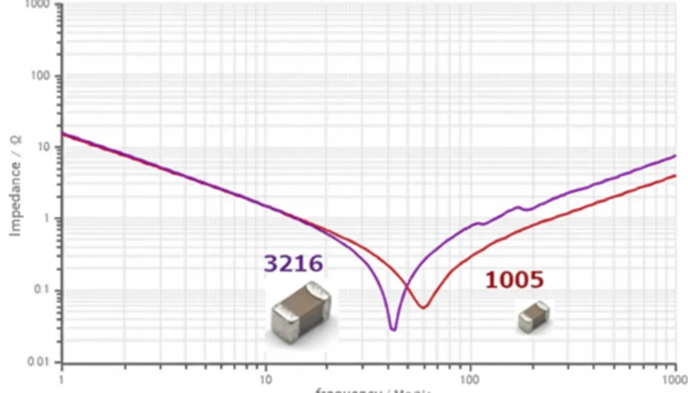
For the same capacitance, a 3216 package may resonate at a different frequency than a 1005 package, indicating differences in ESL.
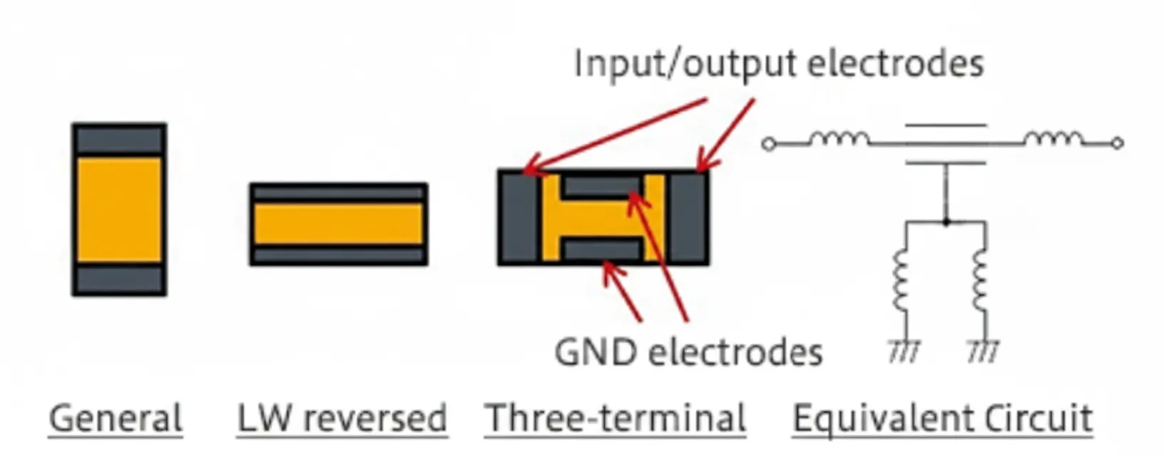
Manufacturers such as Murata and TDK have developed three-terminal capacitors in which the ESL path is arranged to reduce effective series inductance.
5. Capacitor Q factor
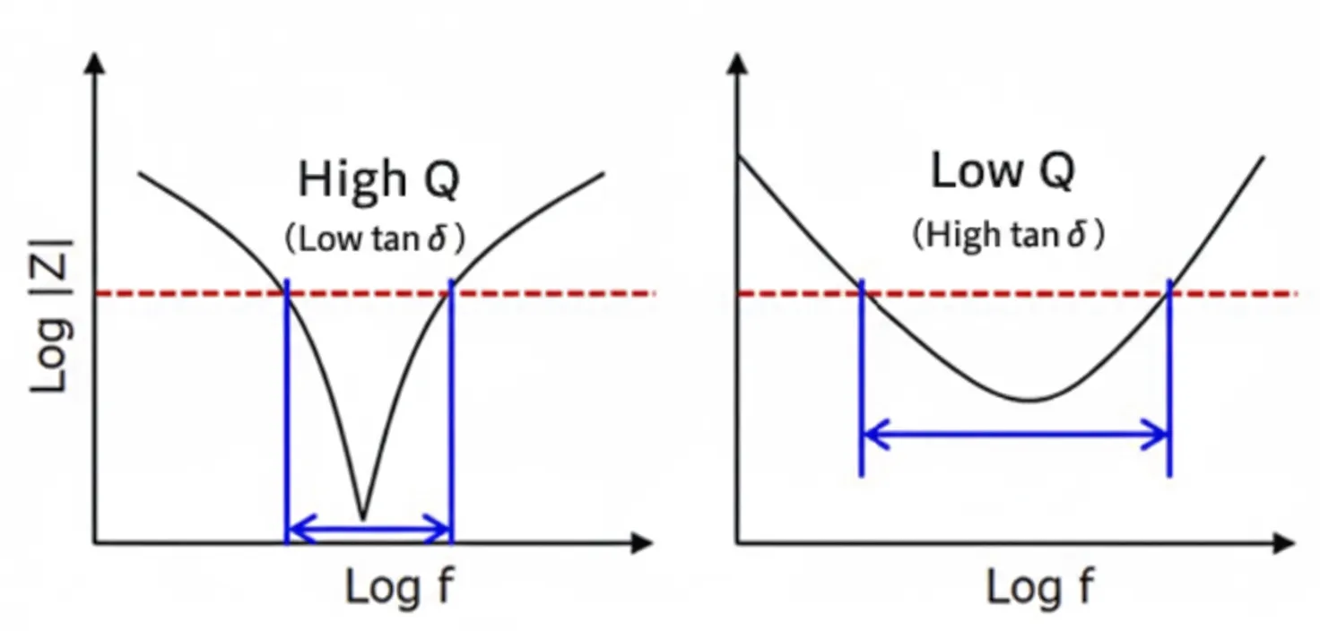
High-Q capacitors exhibit very low impedance near their resonance, but their impedance rises sharply outside that band. Lower-Q capacitors maintain relatively low impedance across a wider range, which can be more beneficial for EMC testing.
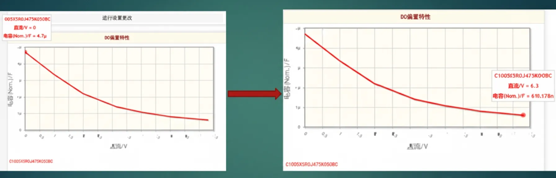
6. Effects of temperature and voltage
Ceramic capacitors can change capacitance significantly under high voltage and high temperature. When capacitance shifts, the self-resonant frequency also shifts and filter performance can degrade, so consider temperature and voltage coefficients when selecting capacitors.