 ALLPCB


Introduction
ISO 7637 is a frequently encountered automotive electronics standard. This article provides a concise overview of the standard's main content to help select targeted solutions.
Test Pulse Classification
Pulse 1
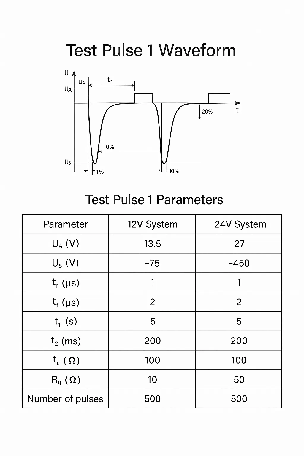
Pulse 1 represents the transient that occurs when an inductive load is disconnected from a supply. It applies to modules that are directly parallel to an inductive load in a vehicle. The P1 pulse has relatively high source impedance (10 to 50 ohm), elevated voltage levels (tens to hundreds of volts), a fast leading edge (microsecond range), and a relatively wide duration (millisecond range). Within ISO 7637-2 it is a medium-speed, medium-energy transient that can cause both interference (erroneous operation) and destructive effects (component damage) on the device under test.
Pulses 2a and 2b
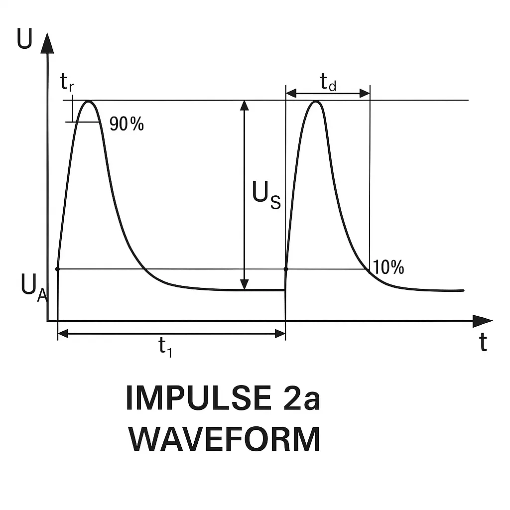
Pulse 2a simulates the transient caused when current in a device parallel to the module is suddenly interrupted due to harness inductance. P2a is a fast, low-energy positive pulse that behaves similarly to P1 but with opposite polarity.
Pulse 2b simulates the transient when a DC machine acting as a generator is disconnected, for example when the ignition switch is opened. P2b has a voltage comparable to the system supply, a relatively slow leading edge (millisecond range), a very wide duration (up to seconds), and very low source impedance. Within ISO 7637-2 it is characterized as a low-speed, high-energy transient focused on destructive effects to components. P2b is similar in effect to P5 but with lower voltage and wider pulse width.
Pulses 3a and 3b
Pulse 3 series simulate switch-induced transients. Their characteristics are influenced by harness distributed capacitance and inductance. P3 consists of a series of high-speed, low-energy subpulses that commonly cause erroneous operation in devices using microprocessors or digital logic control.
Pulse 4
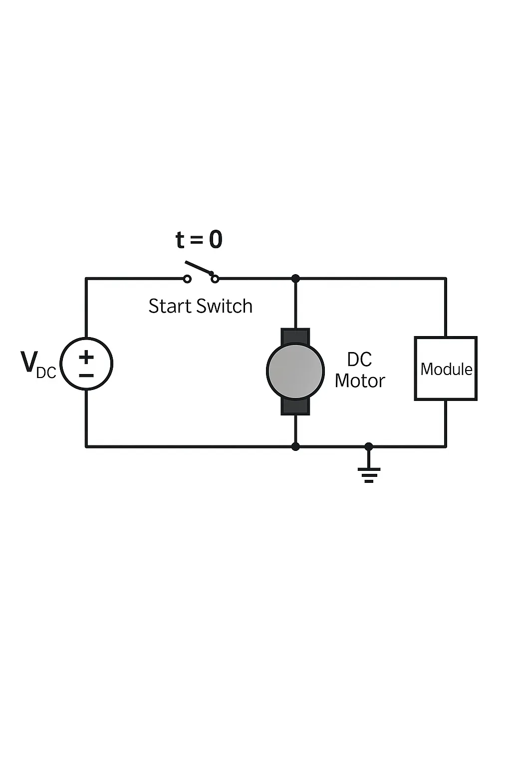
Pulse 4 simulates the voltage drop on the supply when the starter motor circuit is energized, excluding starter-related spikes. When the engine starter is activated, supply voltage may fall, generating Pulse 4. P4 is intended to test erroneous operation during voltage dips, with particular focus on devices containing microprocessors to check for data loss and software disruption.
Pulses 5a and 5b
Pulses 5a and 5b simulate load dump transients. A load dump occurs when the battery is disconnected while the alternator is producing charging current and other loads remain connected. The alternator current is large before disconnection; when the battery is disconnected the current drops suddenly, producing a back EMF. The amplitude of the load dump depends on alternator speed and field excitation. Pulse width depends on the excitation circuit time constant and pulse amplitude. Modern alternators often include internal suppression diodes that clamp load dump amplitude.
Causes of a load dump include cable corrosion, poor contact, or accidental disconnection from the battery while the engine is running.
P5 pulses have high amplitude (typically 100 to 200 V relative to system voltage), long duration (hundreds of milliseconds), and very low source impedance (a few ohms or less), making them high-energy transients. ISO 7637-2 uses P5 to test both immunity and potential destructive effects on device components.
Functional Status Classification
The following classification applies to assemblies or systems.
A class: The assembly or system performs all intended functions during and after the disturbance.
B class: The assembly or system performs all intended functions during the disturbance; however, one or more parameters may deviate beyond specified limits. All functions automatically return to normal operation after the disturbance. Memory functions should remain at A class level.
C class: The assembly or system does not perform one or more intended functions during the disturbance but automatically returns to normal operation after the disturbance ends.
D class: The assembly or system does not perform one or more intended functions during the disturbance and only returns to normal operation after the disturbance ends and a simple user action or operation cycle resets it.
E class: The assembly or system does not perform one or more intended functions during and after the disturbance and cannot return to normal operation without repair or replacement.
Note: "Function" refers to electrical/electronic system functions.
Notes on Test Severity Levels
a The test pulses are as defined in the standard pulses.
b Values agreed between vehicle manufacturer and equipment supplier.
c Amplitude Ua is the value for each test pulse defined in the standard pulse table.
d Because the minimum number of test pulses is 1, no pulse repetition time is specified. When multiple pulses are applied, a minimum delay of 1 min between pulses should be allowed.
e Severity level considers the alternator load dump at rated speed. If centralized load dump protection is used, apply the specified test pulse 5b and the values given in the relevant table.
f The number of pulses or test duration for endurance testing.
g Severity levels I and II are removed because these levels do not ensure sufficient immunity in road vehicles.
Determining Pulse Severity and Functional Class
Manufacturer and user should specify the device's functional class and the required test pulse severity level to define the device application.
If test pulses do not reflect the actual conditions the device will experience in-vehicle, they may be disregarded.
C-class functional failures are acceptable for devices that do not need to operate during a specific pulse (for example, a turn-signal flasher during engine start).
D-class functional failures are acceptable for devices whose failures do not cause customer complaints or inconvenience.
E-class failures are primarily used for reporting purposes and are generally unacceptable except in special circumstances.
For full details, refer to ISO 7637-2. This article provides a brief analysis only.


