 ALLPCB


Overview
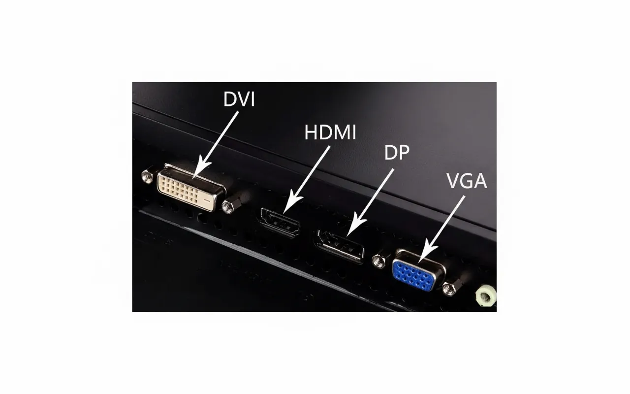
HDMI generally refers to a high-definition video interface and is used in set-top boxes, televisions, laptops, game consoles, AV receivers, digital audio devices, and other equipment. HDMI is a digital video and audio interface technology that can transmit audio and video signals simultaneously.
EMC requirements
The very high data rates and compact connector size of HDMI impose strict EMC requirements. Poor EMC design of an HDMI interface can affect the following EMC test items:
| Port test item | Description | Basic test level | Affected EMC items in the circuit | Remarks |
|---|---|---|---|---|
| RE (Radiated Emission) | Radiated interference along communication lines | CISPR 22 CLASS B | Affects | Must be considered for all application environments |
| ESD (Electrostatic Discharge) | ESD immunity of communication ports | Contact +/-4 kV, Air discharge +/-8 kV | Affects | Must be considered for all application environments |
| RS (Radiated Susceptibility) | Radiated immunity | 3 V/m | Affects | |
| EFT (Electrical Fast Transient) | Pulse-group immunity of communication ports | +/-1000 V | Affects | Consider for long cable runs or environments with many nearby interference sources |
HDMI interface circuit design
Typical HDMI EMC design circuit (Figure 1)
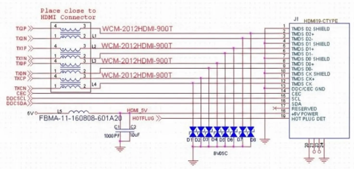
- L1 to L4: It is recommended to use dedicated HDMI common-mode chokes with an impedance of 90 Ω at 100 MHz. Ordinary common-mode inductors often have large parasitic capacitance, which can cause TMDS differential impedance mismatch test failures.
- D1 to D8: ESD protection devices should have low capacitance to avoid degrading signal transmission quality.
- L5: It is recommended to use 600 Ω at 100 MHz. Also note that HDMI Tx tests typically connect a load that draws 55 mA and then measure the output voltage, which must be between 4.8 V and 5.3 V. If a 10 Ω series resistor is added, the output becomes 5 - 10 x 0.055 = 4.45 V, which is less than 4.8 V and will fail the test. C1 and C2 are power filter capacitors; C2 can also help stabilize the HDMI supply voltage.
HDMI interface PCB design
- Place components compactly and according to signal flow, following the principle "protection before filtering". Place ESD protection devices close to the connector, followed by the common-mode choke.
- Each differential pair should be routed parallel and length-matched, surrounded by ground and stitched to the ground plane with vias. Minimize layer changes, since different layer impedances and vias can degrade differential transmission and introduce common-mode noise. Avoid 90-degree bends; use circular arcs or 135-degree bends instead.
- When performing PCB copper pour, provide a clearance cutout under protective devices and the common-mode choke.


