 ALLPCB


1. Background
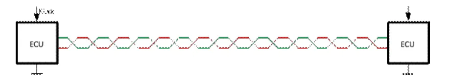
Legacy bus systems such as LIN, controller area network (CAN), CAN-FD, and FlexRay operate using unshielded cables. As data rates increase, signal voltage amplitudes decrease, making these systems:
- More sensitive to noise.
- More susceptible to crosstalk and noise coupling effects.
Ethernet and high-speed SerDes communication have power spectrums extending into the GHz range, which can potentially interfere with in-vehicle radio systems.
Shielded cables are now considered a potential solution. They are already used in automobiles for specific applications, such as radio antennas for analog data. Today, they are also used for data communication lines near radio antennas to protect services like:
- A/FM: Amplitude/Frequency Modulation
- DAB: Digital Audio Broadcasting
- DVB: Digital Video Broadcasting
1.1 Goals of Using Shielded Cables
The purpose of using shielded cables is to prevent noise from affecting sensitive subsystems by achieving the following objectives:
- Reduce capacitive coupling interference caused by electric fields.
- Provide a low-impedance path to ground for common-mode interference.
- Mitigate radiated magnetic fields from inductive coupling.
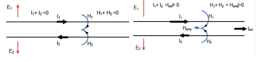
- For shielded twisted pair (STP) cables, this is primarily achieved by twisting the signal conductor pairs.
- For single-core cables, radiation can be canceled if the current on the shield is equal and opposite to the current on the signal conductor.
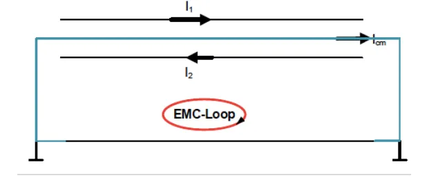
- Gain additional EMC margin through proper loop area reduction and shield termination, which improves coupling attenuation (addressing imbalance and shield effectiveness).
A key consideration is preventing and eliminating coupled magnetic field noise. This is closely related to the shield's ground loop area and termination method. Therefore, the effectiveness of cable shielding against magnetic field noise is achieved by reducing the loop area and implementing proper shield termination.
2. Implementation in Legacy and Modern Systems
2.1 Legacy Digital Audio Broadcasting (DAB) Frequencies
Traditional bus systems like LIN, CAN, CAN-FD, and FlexRay operate at frequencies below critical bands such as FM or DAB. In the past, the amplitude modulation (AM) band was more critical for EMC challenges.
Modern digital systems present new challenges. For instance, DAB requires high-quality radio reception. To ensure this, radio antenna designers have increased the sensitivity of corresponding antennas.
Caption: Power spectrum in a rural area of Bavaria, showing DAB is 15 dB lower than FM stations.
2.2 Historical Impact on DAB Frequencies
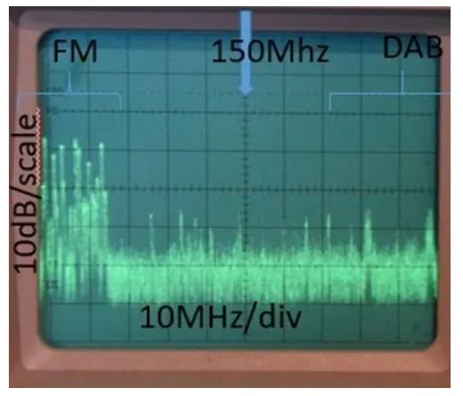
The following figure shows the effect of a 1000BASE-T1 unshielded twisted pair (UTP) data link on a nearby DAB test receiver.
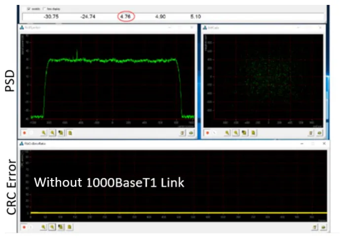
Caption: DAB is susceptible to interference from 1000BASE-T1 data traffic.
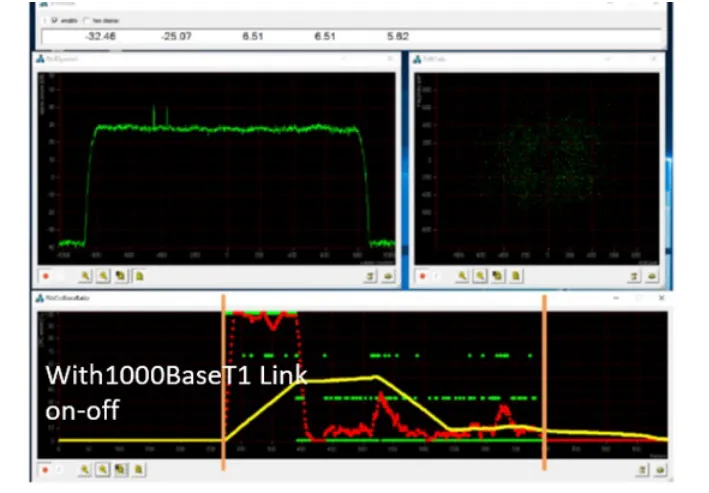
Caption: BMW switched from UTP to STP for its 1000BASE-T1 implementation.
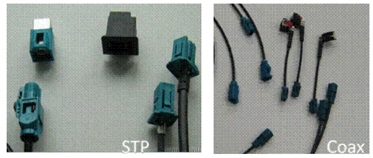
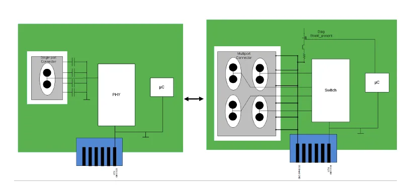
2.3 Multi-Port Connectors: Past and Present
Previous generation multi-port connectors:
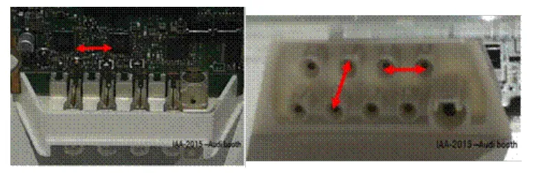
Current generation multi-port connectors:
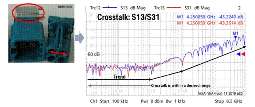
- Below 10 MHz, crosstalk effects are negligible.
- For classic bus systems, an increase of 10 dB per decade from 10 to 100 MHz is not problematic.
- The impact on 100BASE-T1 is minimal, with a 15 dB per decade increase above 100 MHz.
- 1000BASE-T1 and SerDes applications are significantly affected.
2.4 Previous EMI Prevention: Wire Pair Symmetry
In the past, many EMC issues were addressed by using twisted-pair and differential-pair cables. To meet some high-speed signal transmission requirements, a defined cable topology was necessary.
2.4.1 100BASE-T1
This approach worked well for 100BASE-T1 because its power spectral density (PSD) is above the AM band and below the FM band. It relied on wire pair symmetry as the primary method for EMI prevention.
2.4.2 1000BASE-T1
For 1000BASE-T1, with a Nyquist frequency of 375 MHz, the symmetry requirements for cables, connectors, and common-mode chokes became much stricter. Crosstalk emerged as a new primary limiting parameter.
3. Challenges of Cable Shielding
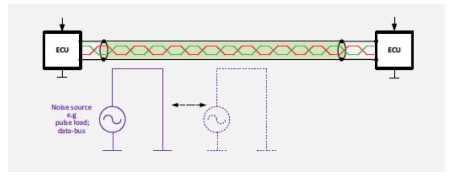
3.1 Expected Noise Coupling Mechanisms
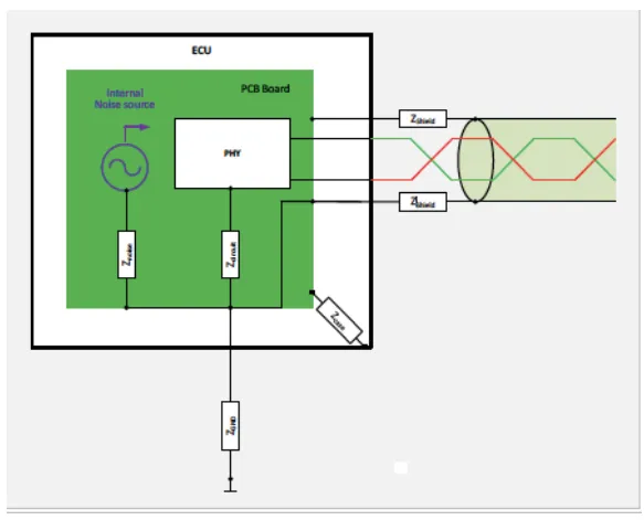
Noise generated within an ECU
Direct noise source coupling to ground
Noise coupling through ground distribution:
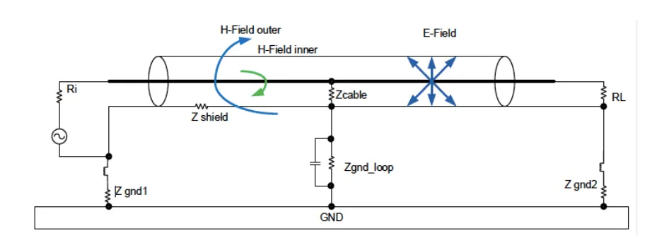
3.2 Example of Inductive Noise Coupling onto a Cable Shield
3.2.1 Noise Coupling from Source to Shield Along the Channel
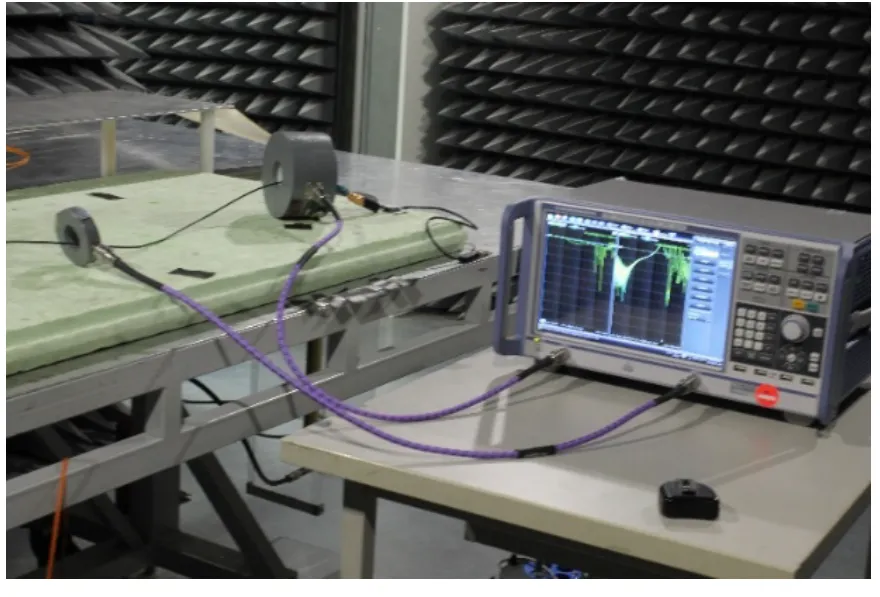
3.2.2 Test Setup
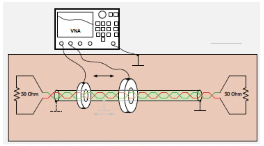
Noise Coupling Insertion Loss:
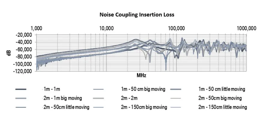
- Noise coupling increases up to approximately 25 MHz.
- It then stays at a certain baseline level but exhibits resonance.
- Resonance frequency varies with cable length and the length of its ground connection, acting as a second-order effect of the noise source.
- Additional grounding terminals change the resonance.
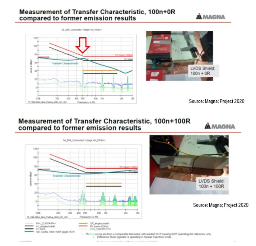
3.3 Do Shielded Cables Prevent Ground Resonance?
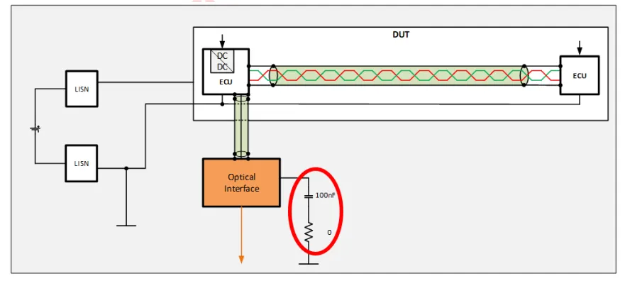
3.3.1 EMC Test Setup

An initial evaluation of test results showed no anomalies. However, EMI noise on the optical interface was later observed to exceed limits in the kHz range. Noise from a DC/DC converter within the ECU was coupling to the optical interface's ground line. A resistor was added along the ground line to mitigate this internal ECU noise. This highlights the need to pre-emptively check the resonance and impedance behavior of the grounding system.
Conclusion: Cable shields can neither prevent nor eliminate ground resonance.
4. Methods to Prevent Shielding Interference
4.1 Prioritizing the System Grounding Concept
To prevent cable shielding interference early in the design process, a specific system grounding configuration must be defined during the initial system design phase.
4.1.1 Overall System Grounding Scheme
Define grounds based on signal type, frequency, and voltage level.
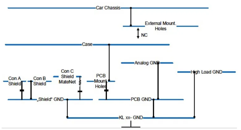
4.1.2 Defining Grounding Schemes within Subsystems
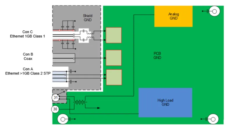
4.1.3 Correlation Between System and Subsystem Grounding
The system-level grounding implementation must be correlated with the subsystem-level implementation.
4.2 Key Considerations for Shield Termination and Ground Loops
An AC coupling capacitor should be used at the second end of the shield. This helps maintain the shield connection at high frequencies while breaking the ground loop at low frequencies, which helps minimize magnetic fields.
A low-impedance path for the shield ground is critical for maximizing effectiveness.
The ground loop in the field acts as a receiving or transmitting monopole antenna, leading to conducted and radiated micro-coupling.
Reducing the shield ground loop area helps minimize electromagnetic induction, thereby reducing generated noise.
5. Conclusion
The ability to use shielded cables is crucial for current and future high-data-rate communication systems. However, a correct and well-planned system implementation approach is essential. The process should begin by defining the overall system grounding configuration, which then informs the general shield grounding method.
Key takeaways:
- Ground planes are often not ideal and can cause impedance variations.
- Cable shields have minimal effect on inductively coupled noise but are effective at eliminating electric field noise sources.
- Defining the system grounding configuration in the initial design phase is critical.
- Single-point shield grounding within a subsystem is beneficial for reducing common ground impedance.
- Multi-point system grounding schemes tend to perform better at high frequencies.
- Cable shield effectiveness is heavily influenced by how it is terminated.
- A low-impedance shield ground path is essential for achieving maximum shielding benefits.
- Cable shield implementation should also target the root noise source.


