 ALLPCB


1. Initial Test Results
During its first EMC compliance test, the "Coconut1" product failed radiated emissions, ESD, and surge immunity tests. This article will focus on troubleshooting the radiated emissions failure.
1.1 Radiated Emissions Failure
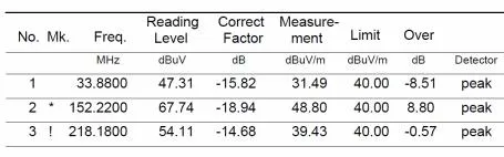
Significant failures were observed at 50 MHz, 100 MHz, 130 MHz, and 200 MHz, with the peak at 130 MHz exceeding the limit by 19 dB. To isolate the source, the board was powered with only the switching power supply (SMPS) section active. The emissions were still severe, particularly around 150 MHz. The following graph shows the results for vertical polarization, which were consistently worse than horizontal polarization throughout the tests. Therefore, this analysis will focus on the vertical results.
2. Troubleshooting Radiated Emissions
2.1 Locating the Noise Source
2.1.1 Based on the frequency of the emissions, the RF module and downstream LDO circuits were ruled out as the source. Reviewing the operating frequencies of the entire system, the likely culprits were the MCU's 8 MHz crystal oscillator and the upstream SMPS.
2.1.2 After the initial failure at the compliance lab, we powered down the RF module, the MCU, and all its peripherals (including the crystal oscillator). The emissions remained above the limit, confirming that the SMPS was the source of the problem.
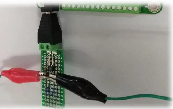
2.1.3 Back in the lab, we focused on finding the exact origin of the radiation. Using an oscilloscope probe as a near-field probe, we quickly scanned the board for areas of high emission.
Figure 2-1: Simple Near-Field Probe Principle
Clipping an alligator clip to an oscilloscope probe tip creates a detection loop. By moving this loop 1-2 cm above the PCB, any area with high-frequency interference will generate a changing magnetic field. This field induces a voltage in the loop. With the oscilloscope set to "persistence" mode, the waveform will rise significantly over the strongest radiation source. A multi-turn air-core coil can also be used for higher sensitivity.
Using this method, we quickly discovered that the radiation was strongest above the SMPS controller IC. The component immediately adjacent to it was a Schottky diode serving as the freewheeling diode. Since the MOSFET is integrated into the SMPS IC, we couldn't measure its switching waveform directly. Instead, we measured the voltage across the freewheeling diode.
Figure 2-3: The ringing, circled in red, shows significant overshoot. Zooming in on this part of the waveform revealed an oscillation frequency of 122 MHz (Figure 2-4), which is very close to the 130 MHz peak seen in the emissions test! Further analysis indicated this ringing was caused by the diode's reverse recovery. The simplest way to eliminate this voltage ringing is to add an RC snubber circuit in parallel with the diode (D2).
2.2 Selecting RC Snubber Parameters
After experimentation, a combination of a 2200 pF capacitor and a 10 Ω resistor was chosen. Experiments showed that a larger capacitance reduces the voltage spike, but it also slows the voltage's falling edge (green arrow in Figure 2-7) and reduces the number of subsequent resonant cycles. This subsequent resonance is normal under light load conditions, as the LC resonant frequency (f) is inversely proportional to capacitance (C).
It is critical to select a resistor with an adequate power rating. If the resistor's power rating is too low, it will be destroyed. A simple way to determine the required rating is to use a 1206 10 Ω resistor temporarily and measure the RMS voltage across it with an oscilloscope. The power can then be calculated using P = V2rms / R. In this case, VRMS was approximately 1V, resulting in a calculated power of 0.1W. To be safe, a 50% derating factor was applied, requiring a resistor rated for at least 0.2W. A 1210 package resistor was ultimately selected.
Figures 2-5 and 2-6 show the freewheeling diode voltage waveforms under heavy and light loads, respectively. The addition of the RC snubber circuit completely resolved the voltage ringing. Figure 2-7 shows the rising edge without any oscillation.
2.3 Mitigation Strategies
Although the RC snubber showed promising results, we could not assume the radiated emissions problem was solved. Many factors influence EMC test results, so it is best to have multiple solutions ready before returning to the compliance lab.
2.3.1 RC Snubber Circuit
The RC snubber circuit addresses the noise at its source and was expected to have a positive impact on the test results.
2.3.2 Ferrite Core
Placing a clamp-on ferrite core on the power cable is a quick way to verify if the radiation is common-mode. This method adds impedance to the common-mode current path, attenuating the noise.
2.3.3 Common-Mode Choke
The original design did not include a common-mode choke at the power input, initially to save costs as EMC certification was not a requirement. When market demands changed, we had to address the emissions problem, but there was no space left on the PCB for a choke. Modifying the PCB without being certain of the choke's effectiveness was not practical. Instead, we built a small external EMI filter board (Figure 2-8). To ensure a reliable connection, it was fitted with a DC barrel jack to interface with the product's power input, with the output connected via alligator clips to test points TP5 and TP6.
2.3.4 Differential-Mode Choke
A similar external EMI filter using a differential-mode choke was also prepared. This filter primarily targets differential-mode radiation. Its schematic and construction are nearly identical to the common-mode filter, with the only difference being that L2 is replaced by two separate inductors.
2.4 Compliance Lab Testing
With four potential solutions, we planned the testing sequence at the EMC lab based on ease of implementation. Solution 2 (ferrite core) was the easiest, followed by solutions 3 and 4 (external filters). Solution 1 (RC snubber) was the most involved, requiring disassembly and soldering. The testing order was therefore set as 2 -> 3/4 -> 1.
2.4.1 Baseline Measurement
First, we obtained a baseline measurement of the unmodified product.
2.4.2 Adding a Ferrite Core
The quarter-wavelength of 123 MHz is 0.6 m, which is very close to the length of the power cable. This suggested the cable was acting as an antenna for common-mode noise. The simplest countermeasure is to attach a ferrite core to the power cable.
To increase its effectiveness, we looped the power cable through the ferrite core once. Comparing Figure 2-9 (baseline) and Figure 2-10, the improvement in vertical emissions is dramatic. The 123 MHz peak was eliminated, leaving only a minor failure of 0.9 dB around 228 MHz. This confirmed the issue was primarily common-mode radiation.
Since a common-mode choke should achieve a similar result, we considered it as a permanent solution. This was preferable for two reasons: first, the product's aesthetics would not allow for a bulky external ferrite core; second, the specific model of the ferrite core used (procured from an online retailer) was unknown.
2.4.3 Adding a Common-Mode Choke
After removing the ferrite core, we connected the external EMI filter. We had prepared two versions of the filter, using two different TDK ACM4520 series common-mode chokes: ACM4520-231-2P-T000 and ACM4520-421-2P-T000. Their impedance vs. frequency curves are shown in Figure 2-11.
Below 300 MHz, the '421' choke has higher overall impedance than the '231'. Since the problematic frequencies were below 300 MHz, we hypothesized that the filter with the '421' choke would provide better suppression. The test results confirmed this hypothesis, as shown in Figures 2-12 and 2-13. The red waveform represents the '231' filter, and the black represents the '421' filter. The '421' choke provided lower emissions across the 100-300 MHz range. However, even the '231' choke provided sufficient margin. The lab technician kindly overlaid the two plots for a direct comparison.
2.4.4 Effect of the RC Snubber
Before testing the RC snubber solution, the external EMI filter was removed. Our lab tests suggested 2200 pF was the optimal capacitance. What would be the effect of a smaller capacitor?
1. R = 10 Ω, C = 1000 pF
Comparing Figure 2-15 with the baseline data (Figure 2-9), it is clear that the RC snubber alone provides a significant improvement, though with insufficient margin. Based on our lab results, we re-tested with the 2200 pF capacitor.
2. R = 10 Ω, C = 2200 pF
Comparing Figures 2-15 and 2-16 shows that the capacitor value in an RC snubber is critical and has a major impact on radiated emissions test results.
2.5 The Final Solution
By combining the EMI filter (using the '231' choke for its higher DC current rating) and the RC snubber circuit (10 Ω + 2200 pF) on the product board, the final test results were nearly perfect. The radiated emissions issue was successfully resolved.
3. Principles of EMI Suppression
3.1 Right-Hand Rule
The right-hand rule helps determine the direction of the magnetic field lines for a straight wire and a solenoid.
1. For a solenoid (right image): If your fingers curl in the direction of the current, your extended thumb points in the direction of the magnetic field.
2. For a straight current-carrying wire (left image, detailed in Fig 2-18): If your thumb points in the direction of the current, your curled fingers indicate the direction of the magnetic field. The magnetic field lines form concentric circles around the wire, becoming denser closer to the center. Because air has low magnetic permeability, the field lines spread out over a large area, and the induced magnetic field (B) is weak.
3.2 How Ferrite Cores Work
When a ferrite core is clamped onto a power cable (Figure 2-20), two types of current are present: differential-mode current (Id) and common-mode current (Ic). The differential-mode currents are equal in magnitude but opposite in direction, while the common-mode currents are equal in both magnitude and direction.
3.2.1 Effect on Common-Mode Current
Applying the right-hand rule to the two wires carrying common-mode current (left side of the diagram), we see that the magnetic fields they generate are in the same direction (clockwise), thus reinforcing each other. The high permeability of the ferrite material provides a low-reluctance path for the magnetic flux, confining most of it within the core. This strong magnetic coupling results in a much larger induced magnetic field (B) compared to wires in open air. For a given change in current (Δi), the change in magnetic field (ΔB) is much greater, which means the inductance (L) is also much greater. Inductors oppose changes in current (Δi/Δt), and since high-frequency radiation is caused by rapid current changes, the ferrite core effectively suppresses common-mode noise. The noise energy is dissipated as heat within the core material due to eddy currents.
3.2.2 Effect on Differential-Mode Current
For differential-mode currents (right side), the currents flow in opposite directions. The magnetic fields they generate are equal in magnitude but opposite in direction. These fields cancel each other out within the core, resulting in a net magnetic field (B) of nearly zero. The ferrite core presents almost no inductance to differential-mode currents and therefore does not suppress them.
3.3 How Common-Mode Chokes Work
Based on the previous analysis and the right-hand rule, we can conclude that a common-mode choke acts as an inductor for common-mode currents but appears as a simple wire (zero inductance) for differential-mode currents.
In reality, common-mode chokes have some leakage inductance. Ideally, the opposing magnetic fields from differential-mode currents would cancel out completely within the core. However, a small portion of the magnetic flux lines "leaks" out of the core and completes its path through the air (red oval in the diagram below). This leakage flux is not canceled and creates a small series inductance. This means the choke also presents some impedance to differential-mode currents. This leakage inductance (Lk) is often beneficial, as it can help suppress differential-mode noise, sometimes eliminating the need for a separate differential-mode choke in the input filter.
3.4 The Effect of Winding Turns
It is well-known that more turns on a common-mode choke increase its inductance, which should provide stronger suppression of common-mode noise. However, this is not always true. With too many turns, the parasitic capacitance between the windings (inter-winding capacitance) becomes significant. According to the parallel plate capacitor formula, more turns on the same core require the windings to be closer together (smaller distance 'd'), which increases this parasitic capacitance.
As shown in Figure 2-22, this total equivalent capacitance provides a low-impedance path for high-frequency common-mode noise currents (red path), allowing them to bypass the inductor and radiate externally. This effect can render the choke ineffective at high frequencies. For this reason, in applications requiring very high inductance, it is often better to use two or more chokes in series to create a multi-stage filter, rather than one large choke with many turns.
3.5 I-core vs. Shielded Inductors
The right-hand rule can also be used to understand the difference between I-core (bobbin) inductors and shielded inductors.
A shielded inductor is essentially an I-core inductor enclosed in a ferrite shell. This shell contains the magnetic flux lines, significantly reducing radiated interference compared to an I-core inductor. The magnetic flux of an I-core inductor must complete its path through the surrounding air, causing the field to spread out and potentially interfere with other components.
However, I-core inductors remain popular for several reasons. They are inexpensive, and the long air gap in their magnetic path makes them resistant to saturation at high currents, allowing them to achieve very high inductance values. Shielded inductors rarely exceed the mH range and have poorer thermal dissipation due to their enclosed structure. The choice between them depends on the specific trade-offs an engineer is willing to make for their application.


