ALLPCB


Understanding vibration analysis of electronic PCB components is crucial for ensuring the reliability and performance of electronic devices, especially in harsh environments like industrial, automotive, or aerospace applications. This blog post dives deep into how vibrations impact printed circuit boards (PCBs), the importance of designing for vibration isolation, and practical techniques to protect your electronic systems. Whether you're exploring how to design a PCB for vibration isolation, considering a flexurally suspended body for PCBs, or testing electronic PCB boxes, we've got you covered with actionable insights.
What Is Vibration Analysis for PCB Components?
Vibration analysis involves studying how mechanical vibrations affect the structural integrity and functionality of electronic components on a PCB. Vibrations can come from external sources like machinery, transportation, or environmental factors, and they can lead to issues such as solder joint failure, component detachment, or signal interference. By analyzing vibrations, engineers can predict potential failures and design solutions to minimize risks.
In this guide, we'll break down the key aspects of vibration analysis, including why it matters, how to test for it, and strategies to isolate vibrations effectively. Our focus on long-tail keywords like "design PCB for vibration isolation," "flexurally PCB suspended body," "electronic PCB boxes," and "vibration isolation PCB test" ensures you get specific, targeted advice for your projects.
Why Vibration Analysis Matters for PCB Design
PCBs are the backbone of most electronic devices, and their components are often delicate. Vibrations can cause mechanical stress, leading to micro-cracks in solder joints or even complete failure of critical parts like capacitors or connectors. In high-stakes applications—think aerospace systems or medical devices—a single failure due to vibration can have catastrophic consequences.
For instance, in automotive electronics, PCBs are exposed to constant vibrations from engine operation and road conditions. Studies show that up to 20% of electronic failures in vehicles are linked to mechanical stress from vibrations. By conducting vibration analysis, engineers can identify resonant frequencies—specific vibration frequencies where the PCB or its components amplify the shaking effect—and design around them to prevent damage.
Vibration analysis also helps in meeting industry standards. Many sectors require PCBs to pass rigorous tests, such as MIL-STD-810 for military applications, which includes vibration testing at frequencies ranging from 5 Hz to 2000 Hz. Understanding these requirements early in the design phase saves time and cost during production.
Key Factors Affecting PCB Vibration
Several factors influence how vibrations impact a PCB. Knowing these can help in designing more resilient boards:
- Component Placement: Heavy or tall components like transformers or large capacitors are more susceptible to vibration-induced stress. Placing them near mounting points or using additional support can reduce movement.
- Board Material: The material of the PCB, often FR-4 with a typical thickness of 1.6 mm, affects its stiffness. Thicker boards or alternative materials like polyimide can offer better resistance to bending under vibration.
- Mounting Method: How the PCB is mounted in its enclosure plays a big role. Rigid mounting can transfer vibrations directly to the board, while flexible or isolated mounting can absorb some of the energy.
- Operating Environment: Environments with high vibration levels, such as near industrial machinery, require more robust designs compared to static office equipment.
Designing PCBs for Vibration Isolation
One of the most effective ways to protect electronic components is to design a PCB for vibration isolation. This approach focuses on minimizing the transfer of mechanical energy to the board and its parts. Here are some practical tips:
1. Use Damping Materials
Incorporate damping materials like silicone pads or rubber grommets between the PCB and its mounting points. These materials absorb vibration energy, reducing the amplitude of oscillations that reach the board. For example, using rubber standoffs with a damping coefficient of around 0.2 can cut vibration transmission by up to 50% at certain frequencies.
2. Optimize Component Layout
Place sensitive or heavy components away from areas of high vibration amplitude, often near the center of the board for symmetrically mounted PCBs. Secure larger components with adhesives or brackets to prevent detachment during high-frequency vibrations (above 100 Hz).
3. Reinforce the PCB Structure
Adding stiffeners or increasing board thickness can reduce flexural bending. A PCB with a thickness of 2.0 mm instead of the standard 1.6 mm can lower the deflection under vibration by approximately 30%, based on finite element analysis studies.
4. Implement Isolation Mounts
Isolation mounts, such as spring-loaded fasteners or elastomeric isolators, can significantly reduce vibration transfer. These mounts work best when tuned to the expected vibration frequency range of the environment, often between 10 Hz and 500 Hz for industrial applications.
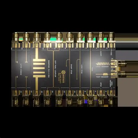
Flexurally PCB Suspended Body: A Unique Approach
A flexurally PCB suspended body refers to a design where the PCB is mounted in a way that allows controlled bending or flexing to absorb vibration energy. This technique is often used in applications where rigid mounting would transfer too much stress to the board.
In this method, the PCB is suspended using flexible supports or springs at specific points, allowing it to move slightly without breaking. This setup reduces the natural frequency of the system, often below 20 Hz, making it less likely to resonate with typical environmental vibrations (usually above 30 Hz). For instance, in aerospace electronics, a flexurally suspended body can protect PCBs from the intense vibrations during launch, which can reach acceleration levels of 10g or more.
To implement this, engineers often use finite element modeling to predict how the PCB will flex under different loads. The goal is to ensure that the bending does not exceed the material’s yield strength, typically around 70 MPa for standard FR-4 boards. This approach requires precise calculations but can extend the lifespan of the PCB significantly in high-vibration environments.
Electronic PCB Boxes: Enclosures for Protection
Electronic PCB boxes, or enclosures, play a vital role in shielding boards from external vibrations. A well-designed enclosure not only protects against dust and moisture but also acts as a first line of defense against mechanical stress.
When selecting or designing an enclosure, consider the following:
- Material: Metal enclosures, such as aluminum with a typical density of 2.7 g/cm3, provide better vibration damping than plastic due to their higher mass and stiffness.
- Mounting Points: Use shock-absorbing mounts inside the box to isolate the PCB from the enclosure’s vibrations. These mounts can reduce transmitted vibration by up to 40% at frequencies above 50 Hz.
- Sealing: Ensure the box is sealed properly to prevent rattling, which can amplify vibrations internally.
Custom enclosures can also be designed with internal ribs or damping layers to further reduce vibration effects. For high-reliability applications, some enclosures are tested to withstand vibration levels up to 5g across a frequency spectrum of 10 Hz to 500 Hz.
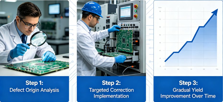
Vibration Isolation PCB Test Techniques
Testing is a critical step in vibration analysis to validate the design and ensure the PCB can withstand real-world conditions. Here are some common vibration isolation PCB test methods:
1. Shaker Table Testing
This involves mounting the PCB on a shaker table that simulates different vibration frequencies and amplitudes. Tests often cover a range of 5 Hz to 2000 Hz with acceleration levels up to 20g, mimicking conditions in automotive or aerospace environments. The goal is to identify resonant frequencies and observe any component failures.
2. Modal Analysis
Modal analysis uses sensors like accelerometers to measure the natural frequencies and mode shapes of the PCB. By understanding how the board deforms under vibration, engineers can adjust the design to avoid resonance. For example, a typical PCB might have a first natural frequency around 60 Hz, which should be far from the operating environment’s dominant vibration frequency.
3. Fatigue Testing
This long-term test subjects the PCB to repeated vibration cycles to simulate years of use. It helps predict when solder joints or components might fail due to fatigue. A common benchmark is testing for 10 million cycles at a specific frequency to ensure durability.
Best Practices for Vibration-Resistant PCB Design
To wrap up the design and testing insights, here are some best practices to ensure your PCB withstands vibrations:
- Simulate early in the design phase using software tools to predict vibration effects.
- Choose components with vibration tolerance ratings suitable for your application.
- Secure all connectors and cables to prevent loose connections under vibration.
- Regularly test prototypes under worst-case scenarios to catch issues before mass production.
Conclusion
Vibration analysis of electronic PCB components is a vital process for ensuring the durability and reliability of electronic systems in challenging environments. By focusing on strategies like designing PCBs for vibration isolation, exploring flexurally suspended body setups, using robust electronic PCB boxes, and conducting thorough vibration isolation PCB tests, engineers can significantly reduce the risk of failure.
At ALLPCB, we understand the importance of creating high-quality, vibration-resistant PCBs for a wide range of applications. Whether you're working on industrial equipment, automotive systems, or aerospace technology, incorporating these vibration analysis techniques into your design process will help you achieve long-lasting, dependable results. Start implementing these strategies in your next project to protect your electronics from the damaging effects of vibrations.