 ALLPCB


Are you facing issues with PCB plasma etching, such as uneven etching, over-etching, under-etching, or residue that won’t go away? Plasma etching is a critical step in PCB fabrication, and even small problems can lead to defective boards or production delays. In this comprehensive guide, we’ll dive into the most common plasma etching defects, their causes, and practical solutions to ensure high-quality results in your PCB manufacturing process. Whether you’re troubleshooting uneven etching or struggling with residue removal, we’ve got you covered with actionable tips and insights.
What Is PCB Plasma Etching and Why Does It Matter?
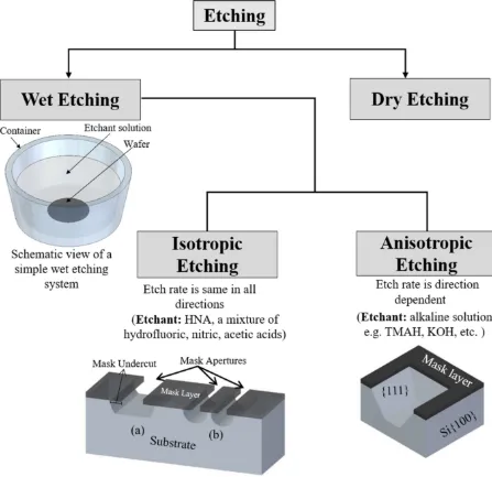
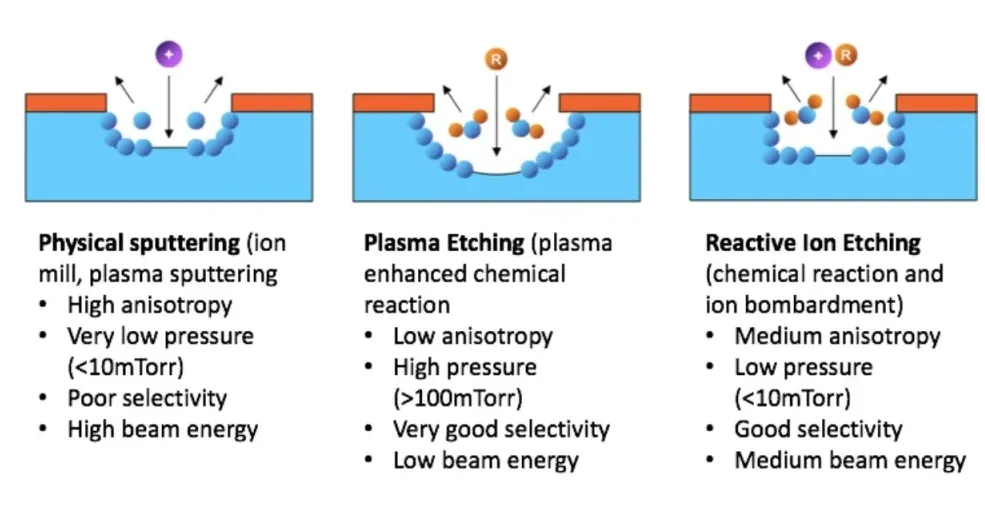
Plasma etching is a dry etching process used in PCB fabrication to remove material from the board’s surface with high precision. Unlike wet etching, which uses chemical solutions, plasma etching relies on ionized gas (plasma) to etch away unwanted material, often in areas like vias or during desmearing and descumming processes. This method offers better control, finer resolution, and is environmentally friendlier since it avoids harsh chemicals.
However, plasma etching is a complex process, and issues like uneven etching or over-etching can compromise the integrity of your PCB. These defects can lead to poor electrical performance, signal loss, or even complete board failure. Understanding and troubleshooting these problems is essential for maintaining quality and efficiency in PCB production.
Common Problems in PCB Plasma Etching
Before diving into solutions, let’s explore the most frequent issues encountered during plasma etching. Identifying the problem is the first step to fixing it. Below are the key defects associated with PCB plasma etching.
1. Uneven Etching
Uneven etching occurs when material is removed inconsistently across the PCB surface. This can result in some areas being over-etched while others remain under-etched, leading to irregular patterns or incomplete circuits. Uneven etching often causes signal integrity issues, as trace widths may vary beyond acceptable tolerances (typically ±10% of the design width, e.g., a 5-mil trace varying by 0.5 mils).
2. Over-Etching
Over-etching happens when too much material is removed, often beyond the intended design. This can thin out copper traces or damage dielectric layers, weakening the board’s structure and electrical performance. For instance, if a trace designed to handle 1 amp of current is over-etched by 20%, its current-carrying capacity could drop significantly, leading to overheating.
3. Under-Etching
Under-etching is the opposite of over-etching, where insufficient material is removed. This leaves unwanted residues or incomplete patterns, potentially causing short circuits or poor connectivity. For example, if vias are not fully desmeared, residual debris can block connections, increasing resistance beyond typical values (e.g., above 50 milliohms per via).
4. Residue Removal Challenges
Residue, such as leftover photoresist or debris from drilling, can remain on the PCB after plasma etching. If not properly removed during descumming, this residue can interfere with subsequent processes like plating, leading to defects. Incomplete residue removal is a common cause of poor adhesion in multilayer boards.
5. Plasma Etching Defects
General plasma etching defects include surface roughness, micro-cracks, or unintended etching profiles. These issues can compromise the PCB’s mechanical strength and electrical properties, often resulting from improper equipment settings or material incompatibilities.
Causes of PCB Plasma Etching Problems
Understanding the root causes of plasma etching issues is critical for effective troubleshooting. Here are the primary factors contributing to common defects.
1. Incorrect Plasma Parameters
Plasma etching relies on parameters like power, pressure, gas composition, and etching time. If the power is too high (e.g., above 500 watts for certain materials), it can lead to over-etching. Conversely, low power (below 200 watts) might cause under-etching. Incorrect gas mixtures, such as an imbalance of oxygen and fluorine-based gases, can also result in uneven etching.
2. Equipment Issues
Worn-out electrodes, uneven gas distribution, or chamber contamination can disrupt the plasma process. For instance, if the gas flow rate varies by more than 5% across the chamber, it can create hotspots, leading to uneven material removal.
3. Material Variability
Not all PCB materials react the same way to plasma etching. Variations in substrate composition, such as differences in epoxy resin or glass fiber density, can affect etching rates. A board with a higher glass content might etch slower, causing under-etching in some areas.
4. Masking and Design Flaws
Poorly applied or low-quality photoresist masks can fail to protect areas meant to remain unetched, leading to over-etching. Additionally, design errors, like traces spaced too closely (below 3 mils), can cause unintended etching due to plasma spillover.
Troubleshooting PCB Plasma Etching: Step-by-Step Solutions
Now that we’ve identified the problems and their causes, let’s explore actionable solutions for troubleshooting PCB plasma etching issues. Follow these steps to resolve common defects and improve your fabrication process.
1. Addressing Uneven Etching
To fix uneven etching, start by calibrating your plasma equipment. Ensure the gas flow is uniform across the chamber, maintaining a variance of less than 2%. Next, check the power distribution—modern systems often allow adjustments to balance plasma density. If the issue persists, inspect the PCB for material inconsistencies. Using a consistent batch of substrates with uniform dielectric constants (e.g., FR-4 with a Dk of 4.2-4.5) can minimize variability. Finally, consider reducing etching time by 10-15% and perform test runs to monitor uniformity.
2. Correcting Over-Etching
Over-etching can be mitigated by lowering the plasma power. For example, if you’re operating at 600 watts, reduce it to 400-450 watts and observe the results. Additionally, shorten the etching duration—start with a 20% reduction (e.g., from 5 minutes to 4 minutes) and adjust as needed. Using a more robust photoresist mask with a thickness of at least 1.5 mils can also protect areas from excessive material removal. Regularly monitor the etch rate, targeting a controlled removal of 0.1-0.2 microns per minute for delicate layers.
3. Solving Under-Etching
For under-etching, increase the plasma power or etching time slightly. If your system is set at 200 watts, try increasing it to 250-300 watts. Extend the etching duration by 10-20% if power adjustments don’t work. Ensure the gas mixture is optimized—adding more reactive gases like oxygen (up to 30% of the mix) can enhance material removal. Clean the chamber regularly to prevent residue buildup that could weaken plasma effectiveness.
4. Improving Residue Removal
Residue removal, or descumming, requires a focused plasma process. Use an oxygen-rich plasma (50-70% oxygen content) at moderate power (300-400 watts) for 2-3 minutes to burn off organic residues like photoresist. For tougher debris, such as drilling smear in vias, combine plasma desmearing with a short wet cleaning step if necessary. Inspect the board under a microscope at 50x magnification to confirm residue is removed without damaging the surface.
5. Preventing General Plasma Etching Defects
To avoid defects like surface roughness or micro-cracks, maintain strict control over plasma parameters. Keep chamber pressure within a tight range (e.g., 50-100 mTorr) to prevent erratic etching profiles. Regularly maintain equipment by replacing electrodes after 500 hours of operation or as per manufacturer guidelines. Finally, use simulation software to predict etching outcomes based on your design and adjust settings accordingly.
Best Practices for Consistent Plasma Etching Results
Beyond troubleshooting specific issues, adopting best practices can prevent problems before they occur. Here are some tips to ensure consistent, high-quality plasma etching in PCB fabrication.
- Regular Calibration: Calibrate your plasma system weekly to maintain uniform gas flow, power, and pressure. A deviation of even 5% in these parameters can lead to defects.
- Material Testing: Test each batch of PCB substrates for etching compatibility. Measure etching rates on a sample board to establish baseline parameters.
- Process Monitoring: Use in-situ monitoring tools to track etch depth and uniformity in real-time. Target a uniformity variance of less than 3% across the board.
- Staff Training: Ensure operators are trained to recognize early signs of etching issues, such as abnormal plasma glow or inconsistent etch patterns.
- Documentation: Keep detailed records of etching parameters and outcomes for each production run. This data helps identify trends and recurring issues.
Advantages of Plasma Etching Over Traditional Methods
While troubleshooting plasma etching can be challenging, it offers significant benefits over wet etching. Plasma etching provides finer control, with resolutions down to 0.5 microns compared to 2-3 microns for chemical methods. It also reduces environmental impact by eliminating the need for toxic etchants. Additionally, plasma processes can handle a wider range of materials, making them ideal for advanced multilayer PCBs with complex designs.
Conclusion: Mastering PCB Plasma Etching for Better Fabrication
Troubleshooting PCB plasma etching doesn’t have to be a daunting task. By understanding common problems like uneven etching, over-etching, under-etching, and residue removal challenges, you can take targeted steps to improve your process. Whether it’s adjusting plasma parameters, maintaining equipment, or adopting best practices, the solutions outlined in this guide can help you achieve consistent, high-quality results in PCB fabrication.
Plasma etching is a powerful tool in modern PCB manufacturing, and with the right approach, you can minimize defects and maximize efficiency. Keep testing, monitoring, and refining your process to stay ahead of potential issues. With these strategies, you’re well on your way to mastering PCB plasma etching troubleshooting and producing top-notch circuit boards.


