ALLPCB


Printed Circuit Boards (PCBs) are the backbone of modern electronics, but when they fail, identifying the root cause can be a daunting task. How can you pinpoint issues like short circuits, component failures, or hidden defects quickly and accurately? The answer lies in advanced imaging technologies. Techniques such as thermal imaging for PCBs, X-ray PCB failure detection, and reverse engineering PCB imaging play a crucial role in PCB failure analysis imaging, helping engineers diagnose problems with precision.
In this comprehensive guide, we’ll explore how these imaging methods assist in troubleshooting PCB failures. From detecting short circuits to uncovering manufacturing defects, we’ll break down each technology, its application, and why it’s essential for effective root cause analysis. Whether you’re an electronics engineer or a quality control specialist, this post will equip you with actionable insights to enhance your PCB troubleshooting process.
Why PCB Failure Analysis Matters
PCBs are intricate assemblies of conductive traces, components, and insulating materials, all working together to power electronic devices. A single failure—be it a short circuit, open trace, or defective component—can halt an entire system, leading to costly downtime or product recalls. According to industry studies, PCB failures account for up to 30% of electronic device malfunctions, making failure analysis a critical step in design, manufacturing, and maintenance.
Traditional troubleshooting methods, like visual inspection or multimeter testing, often fall short when dealing with complex, multilayer boards or hidden defects. This is where PCB failure analysis imaging comes in. By leveraging advanced tools like thermal imaging and X-ray detection, engineers can visualize issues that are invisible to the naked eye, ensuring faster and more accurate diagnosis.

Key Imaging Technologies for PCB Failure Analysis
Imaging technologies have revolutionized the way we approach PCB troubleshooting. Below, we dive into the most effective methods—thermal imaging for PCBs, X-ray PCB failure detection, and reverse engineering PCB imaging—explaining how each aids in root cause analysis.
1. Thermal Imaging for PCB Troubleshooting
Thermal imaging, also known as infrared thermography, is a non-invasive technique that detects heat signatures on a PCB. By using a thermal camera, engineers can identify hot spots caused by excessive current flow, short circuits, or failing components. This method is particularly useful for PCB short circuit detection, as it highlights areas of abnormal heat generation without requiring physical contact with the board.
For example, a short circuit between two traces might cause a localized temperature spike of 50°C or more above the surrounding area. Modern thermal cameras, with resolutions as high as 512x384 pixels, can detect these anomalies with precision, even in densely populated boards. This allows for quick identification of issues like overcurrent in a specific IC or resistor overheating due to poor soldering.
Thermal imaging for PCBs is also valuable during live testing. By powering the board and observing real-time heat patterns, engineers can monitor how components behave under load, revealing intermittent faults that static tests might miss.
Benefits of Thermal Imaging:
- Non-destructive and safe to use on live circuits.
- Quickly identifies hot spots for PCB short circuit detection.
- Reduces diagnostic time by up to 40% compared to manual testing.
2. X-Ray PCB Failure Detection for Hidden Defects
While thermal imaging excels at surface-level analysis, many PCB failures occur within internal layers or under components, where visual or thermal methods can’t reach. This is where X-ray PCB failure detection shines. X-ray imaging penetrates through materials, providing a detailed view of a PCB’s internal structure, including solder joints, vias, and hidden traces.
X-ray systems are indispensable for detecting issues like voids in solder joints, misaligned components, or broken internal traces in multilayer boards. For instance, a poorly soldered ball grid array (BGA) might have voids that reduce electrical conductivity, leading to intermittent failures. X-ray imaging can reveal these defects with micrometer-level precision, often detecting gaps as small as 10 micrometers.
This technology is also critical for quality control in manufacturing. By scanning assembled boards, manufacturers can catch defects early, reducing the risk of field failures. Studies suggest that X-ray inspection can improve defect detection rates by over 60% compared to optical methods alone.
Benefits of X-Ray Detection:
- Reveals internal defects without disassembling the PCB.
- Essential for inspecting complex, multilayer designs.
- Highly accurate for detecting soldering issues and trace breaks.

3. Reverse Engineering PCB Imaging for Design Analysis
Reverse engineering PCB imaging is a powerful tool when dealing with legacy systems or undocumented designs. This process involves creating detailed images of a PCB’s layout, often using a combination of X-ray, optical scanning, and software reconstruction, to recreate schematics or identify failure points.
For example, if a PCB from an older device fails and no design files are available, reverse engineering can map out the board’s traces and components. High-resolution imaging can capture trace widths as narrow as 0.1mm, allowing engineers to rebuild the design or spot manufacturing flaws that led to failure. This method is also used to analyze competitor designs (within legal boundaries) or to update outdated boards for modern standards.
In failure analysis, reverse engineering helps identify design flaws, such as improper trace routing that causes signal interference at high frequencies (e.g., above 1 GHz). By reconstructing the board’s layout, engineers can simulate its performance and pinpoint the root cause of issues like crosstalk or impedance mismatches.
Benefits of Reverse Engineering Imaging:
- Recreates layouts for undocumented or legacy PCBs.
- Helps identify design flaws contributing to failures.
- Supports updates and redesigns for improved reliability.
Practical Applications of Imaging in PCB Short Circuit Detection
One of the most common PCB failures is a short circuit, where unintended electrical connections cause excessive current flow, often leading to overheating or component burnout. PCB short circuit detection is a prime use case for imaging technologies, as shorts can occur on the surface, within layers, or under components.
Thermal imaging is often the first step in detecting shorts. By powering the board and scanning for hot spots, engineers can narrow down the affected area within seconds. For instance, a short between two adjacent traces might generate heat exceeding 70°C, clearly visible on a thermal scan.
If the short is internal or under a component, X-ray PCB failure detection takes over. X-rays can reveal physical bridges between traces or solder splashes that cause shorts, even in boards with up to 16 layers. Once identified, engineers can use targeted repairs, like removing excess solder or rerouting traces, to resolve the issue.
In cases where the short stems from a design flaw, reverse engineering PCB imaging helps. By reconstructing the board’s layout, engineers can check for trace spacing violations—industry standards recommend at least 0.2mm spacing for low-voltage designs to prevent shorts—and redesign the board accordingly.
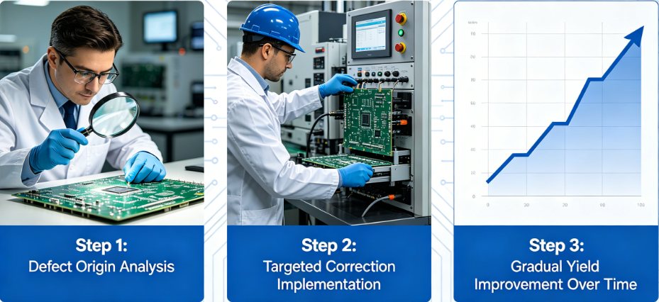
Combining Imaging Technologies for Comprehensive Analysis
While each imaging method has its strengths, combining them often yields the best results for PCB failure analysis imaging. A typical workflow might start with thermal imaging to spot surface-level issues like overheating components or shorts. If the problem isn’t visible, X-ray detection can investigate internal defects or hidden solder issues. Finally, for systemic or design-related failures, reverse engineering imaging provides a full picture of the board’s layout and potential flaws.
This multi-pronged approach reduces diagnostic time and improves accuracy. For example, a study in electronics manufacturing found that combining thermal and X-ray imaging increased defect detection rates by 75% compared to using either method alone. It also minimizes the risk of overlooking subtle issues, ensuring a thorough root cause analysis.
Challenges and Considerations in PCB Failure Analysis Imaging
Despite their advantages, imaging technologies come with challenges. Thermal imaging, for instance, requires a clear line of sight and may struggle with densely packed boards where heat dissipation masks hot spots. X-ray detection, while powerful, involves expensive equipment and requires trained personnel to interpret images accurately. Reverse engineering can be time-intensive, especially for complex boards with hundreds of components.
To overcome these hurdles, engineers should:
- Use high-resolution thermal cameras (e.g., with sensitivity to 0.05°C) for better accuracy.
- Invest in automated X-ray analysis software to speed up defect identification.
- Document PCB designs during production to reduce reliance on reverse engineering.
How Imaging Enhances Quality Control in PCB Manufacturing
Beyond troubleshooting, imaging technologies play a vital role in preventing failures during manufacturing. Thermal imaging can monitor soldering processes in real-time, ensuring components are mounted at optimal temperatures (typically 220-260°C for reflow soldering). X-ray inspection verifies the integrity of solder joints and internal traces before boards leave the factory. These proactive steps reduce failure rates by catching defects early, saving time and costs.
For instance, a manufacturing line implementing X-ray inspection reported a 50% reduction in field failures due to early detection of soldering voids. Such data underscores the value of imaging not just for failure analysis, but as a cornerstone of quality assurance.

Future Trends in PCB Failure Analysis Imaging
As technology evolves, so do the tools for PCB failure analysis imaging. Emerging trends include the integration of artificial intelligence (AI) with imaging systems. AI algorithms can analyze thermal and X-ray images to automatically detect anomalies, reducing human error and diagnostic time. Additionally, portable thermal cameras with higher resolutions are becoming more accessible, making on-site troubleshooting easier than ever.
Another exciting development is 3D X-ray imaging, which provides a layered view of PCBs, enhancing the ability to inspect complex designs. These advancements promise to make failure analysis faster, more accurate, and more cost-effective in the years ahead.
Conclusion: Leveraging Imaging for Effective PCB Troubleshooting
Troubleshooting PCB failures is no longer a game of guesswork. With imaging technologies like thermal imaging for PCBs, X-ray PCB failure detection, and reverse engineering PCB imaging, engineers can uncover the root causes of issues with unprecedented precision. Whether it’s PCB short circuit detection or identifying hidden manufacturing defects, these tools streamline the diagnostic process, saving time and ensuring reliability.
By adopting a multi-technology approach and staying abreast of emerging trends, you can enhance your failure analysis capabilities and prevent costly downtimes. At the core of every successful electronic device lies a robust PCB—and with the right imaging tools, you can keep yours performing at its best.