 ALLPCB


Are you struggling with unreliable connections on your PCB due to cold solder joints? Hot air rework is a powerful technique to fix these issues and restore your board’s functionality. In this comprehensive guide, we’ll walk you through cold solder joint diagnosis, hot air rework solder reflow methods, solder joint inspection techniques, PCB soldering troubleshooting, and effective solder joint repair methods. Whether you’re a hobbyist or a professional engineer, this blog will equip you with practical solutions to ensure strong and reliable solder connections.
What Are Cold Solder Joints and Why Do They Matter?
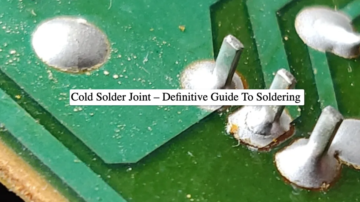
A cold solder joint is a common defect in PCB assembly where the solder fails to properly melt and bond with the component lead or pad. This results in a weak or incomplete connection that can lead to intermittent signals, unstable performance, or complete circuit failure. These issues often develop over time, making them tricky to spot during initial testing.
Cold solder joints typically occur due to insufficient heat during soldering, movement of components before the solder cools, or poor surface preparation. For instance, if the soldering iron temperature is below the melting point of the solder (typically around 183°C for lead-free solder), the joint may look connected but lack the necessary intermetallic bond. This can increase electrical resistance, sometimes exceeding 10 ohms in severe cases, disrupting signal integrity at high frequencies above 100 MHz.
Understanding and fixing cold solder joints is critical for maintaining the reliability of your PCB. Let’s dive into how to identify these defects with effective solder joint inspection techniques.
Cold Solder Joint Diagnosis: How to Spot the Problem
Diagnosing cold solder joints early can save you from costly rework or complete board failure. Here are some proven solder joint inspection techniques to help you identify these defects:
- Visual Inspection: Look for joints that appear dull, grainy, or cracked. A proper solder joint should have a smooth, shiny surface with a concave fillet. Cold solder joints often lack this smooth finish and may show uneven solder distribution.
- Physical Testing: Gently wiggle the component. If it moves easily or feels loose, the solder joint may not be properly bonded. Be cautious, as excessive force can damage the board.
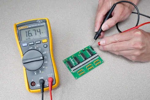
- Electrical Testing: Use a multimeter to check for continuity or high resistance across the joint. Resistance values above 1 ohm on a suspected joint often indicate a problem. For critical circuits, even a slight increase in resistance can affect performance, especially in power delivery systems handling currents above 1A.
- Thermal Imaging: In advanced setups, thermal cameras can detect cold solder joints by showing uneven heat distribution during operation. A poorly bonded joint may overheat due to increased resistance.
By combining these methods, you can pinpoint cold solder joints before they cause major issues. Once identified, the next step in PCB soldering troubleshooting is to repair the joint using the right tools and techniques.
Related Reading: Troubleshooting Cold Solder Joints: A Practical Guide for Electronics Repair
Why Hot Air Rework for Solder Joint Repair?
Hot air rework is one of the most effective solder joint repair methods, especially for surface-mount components (SMDs) and densely populated PCBs. Unlike a soldering iron, which applies heat directly to a single point, a hot air station delivers a controlled stream of heated air to reflow solder across an entire component or joint. This ensures even heat distribution, reducing the risk of thermal damage to nearby components or the board itself.
Hot air rework is particularly useful for reflowing solder on cold joints because it mimics the conditions of a reflow oven used in mass production. By heating the solder to its melting point (typically 217-230°C for lead-free solder), it allows the solder to flow and form a proper bond with the pad and component lead. This method is ideal for modern PCBs with fine-pitch components where precision is critical.
Additionally, hot air rework stations often come with adjustable temperature and airflow settings, giving you control over the process. For example, a typical setting for lead-free solder reflow might be 300°C with moderate airflow to avoid blowing components off the board. This flexibility makes hot air rework a go-to solution for PCB soldering troubleshooting.
Step-by-Step Guide to Hot Air Rework Solder Reflow
Ready to fix those cold solder joints? Follow this detailed guide on hot air rework solder reflow to achieve reliable results. Ensure you have a hot air rework station, flux, and proper safety gear before starting.
- Prepare the Workspace: Work in a well-ventilated area and use a heat-resistant mat to protect your surface. Secure the PCB in a holder to prevent movement during rework.
- Apply Flux: Add a small amount of flux to the cold solder joint. Flux cleans the surface, removes oxidation, and helps the solder flow evenly. Use a no-clean flux for convenience, as it leaves minimal residue.
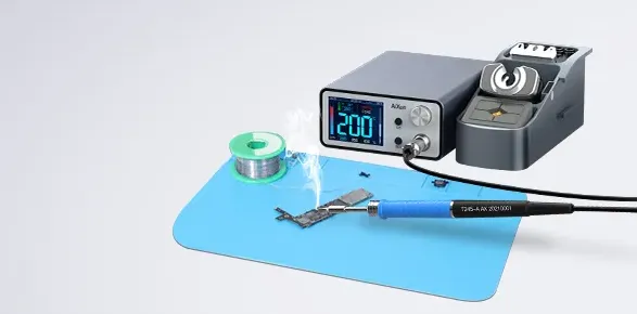
- Set Up the Hot Air Station: Adjust the temperature and airflow based on the solder type. For lead-free solder, set the temperature between 300-350°C and use a low to medium airflow (around 20-30 liters per minute) to avoid displacing components.
- Heat the Joint: Hold the hot air nozzle about 1-2 inches above the joint and move it in a circular motion to evenly distribute heat. Heat for 10-20 seconds until the solder melts and flows smoothly. You should see the joint become shiny as it reflows.
- Cool Down: Allow the joint to cool naturally without blowing air or moving the board. Rapid cooling can cause thermal stress and create new cracks in the solder.
- Inspect the Repair: After cooling, visually inspect the joint for a smooth, shiny finish. Test it with a multimeter to confirm low resistance (ideally below 0.1 ohms).
Following these steps ensures a strong bond and prevents further issues. Hot air rework solder reflow is a skill that improves with practice, so don’t be discouraged if your first attempt isn’t perfect.
Common Challenges in Hot Air Rework and How to Overcome Them
While hot air rework is highly effective, it comes with challenges, especially for beginners. Here are some common issues in PCB soldering troubleshooting and how to address them:
- Overheating Components: Excessive heat can damage sensitive components like microcontrollers or capacitors. To avoid this, use a heat shield or kapton tape to protect nearby parts. Limit heating time to under 30 seconds per joint.
- Solder Not Melting: If the solder doesn’t reflow, your temperature may be too low or the airflow too high, dispersing heat. Increase the temperature by 20-30°C or reduce airflow slightly. Ensure your hot air station is calibrated for accuracy.
- Component Displacement: High airflow can blow small components off the board. Use a lower airflow setting (below 20 liters per minute for tiny SMDs) and secure components with tweezers if needed before heating.
- Uneven Reflow: If the solder reflows unevenly, ensure you’re moving the nozzle in a consistent circular pattern. Applying additional flux can also help the solder spread uniformly.
By anticipating these issues and adjusting your technique, you can achieve consistent results with hot air rework solder reflow.
Preventing Cold Solder Joints in Future Projects
While hot air rework is a great fix, preventing cold solder joints during the initial soldering process is even better. Here are some tips to minimize defects in your PCB assembly:
- Use Proper Heat: Ensure your soldering iron or reflow oven reaches the correct temperature for your solder type. For lead-free solder, aim for 260-300°C during manual soldering to guarantee full melting.
- Clean Surfaces: Before soldering, clean the PCB pads and component leads with isopropyl alcohol to remove dirt or oxidation. This promotes better solder adhesion.
- Avoid Movement: Keep the component and board steady until the solder cools completely. Even slight movement during cooling can disrupt the joint formation.
- Apply Flux Generously: Flux improves solder flow and prevents oxidation during heating. Use it during both initial soldering and rework processes.
- Inspect Regularly: Make solder joint inspection techniques a routine part of your workflow. Catching issues early prevents long-term damage.
Implementing these practices reduces the likelihood of cold solder joints, saving you time and effort on repairs.
Related Reading: The Ultimate Guide to Preventing Cold Solder Joints: Temperature, Technique, and Tools
Advanced Solder Joint Repair Methods for Complex Issues
For more challenging cases, such as multilayer boards or high-density designs, advanced solder joint repair methods may be necessary. Here are two techniques to consider:
- Preheating the Board: For thick or multilayer PCBs, preheating the entire board to 100-120°C before hot air rework can reduce thermal stress. Use a preheat plate or oven to evenly warm the board, then apply hot air to the specific joint. This method minimizes the risk of warping or delamination.
- Adding Fresh Solder: If the existing solder on a cold joint is insufficient or contaminated, remove it with a desoldering braid and apply fresh solder. Then, use hot air to reflow the new solder for a stronger bond. Choose a solder alloy matching the original (e.g., SAC305 for lead-free boards) to ensure compatibility.
These advanced methods require precision and experience but can tackle even the toughest cold solder joint issues on complex boards.
Tools You Need for Effective PCB Soldering Troubleshooting
Having the right tools is essential for cold solder joint diagnosis and repair. Here’s a list of must-have equipment for hot air rework and PCB soldering troubleshooting:
- Hot Air Rework Station: Choose a station with adjustable temperature (up to 400°C) and airflow controls for versatility. Look for models with interchangeable nozzles for different component sizes.
- Multimeter: A reliable multimeter is crucial for electrical testing. Opt for one with high accuracy (within 0.01 ohms) to detect subtle resistance changes in joints.
- Flux and Solder: Keep a supply of no-clean flux and matching solder wire or paste. Ensure the solder matches your board’s specifications (lead-free or leaded).
- Magnifying Tools: A magnifying glass or digital microscope helps with detailed solder joint inspection, especially for tiny SMD components.
- Tweezers and Brushes: Precision tweezers are useful for handling small parts, while brushes help clean flux residue after rework.
Investing in quality tools ensures accurate diagnosis and efficient repairs, making your workflow smoother and more effective.
Conclusion: Master Cold Solder Joint Repairs with Hot Air Rework
Cold solder joints can compromise the performance and reliability of your PCB, but with the right techniques, they’re entirely fixable. By mastering cold solder joint diagnosis, leveraging hot air rework solder reflow, and applying proper solder joint inspection techniques, you can tackle PCB soldering troubleshooting with confidence. Whether you’re repairing a single joint or maintaining a complex board, the solder joint repair methods outlined in this guide provide a solid foundation for success.
At ALLPCB, we’re committed to supporting engineers and hobbyists with resources and solutions for every stage of PCB design and assembly. Use these tips to ensure your projects are built on strong, reliable connections. With practice and the right tools, hot air rework can become your go-to method for rescuing boards from cold solder joint issues.


