 ALLPCB


In the fast-paced world of electronics manufacturing, ensuring the quality and functionality of printed circuit boards (PCBs) is crucial. One of the most effective methods for achieving this is through flying probe testing components. But what exactly is flying probe testing, and how does it help with PCB component testing? In this comprehensive guide, we’ll explore the ins and outs of flying probe testing, with a focus on diagnosing components like resistors and capacitors, and why it’s a game-changer for PCB quality assurance.
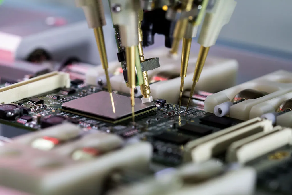
At its core, flying probe testing is a non-invasive, fixtureless testing method used to check the electrical integrity of PCBs. Unlike traditional testing methods that require custom fixtures, flying probes use movable test probes to make contact with specific points on the board, testing individual components and connections. This makes it ideal for prototype testing, low-volume production, and complex boards. Whether you’re testing a flying probe testing resistor or a flying probe testing capacitor, this method offers precision and flexibility. Let’s dive deeper into how it works and why it matters.
What is Flying Probe Testing and Why Does It Matter?
Flying probe testing (FPT) is a modern testing technique used in PCB manufacturing to verify the functionality of both bare boards and fully assembled PCBs. Introduced in the late 1980s, this method employs multiple test probes that “fly” over the board, making contact with designated test points to measure electrical characteristics. Unlike in-circuit testing (ICT), which relies on a fixed bed-of-nails fixture, flying probe testing is fixtureless, saving time and cost for small batches or designs that frequently change.
Why does this matter? In today’s electronics industry, where designs are becoming increasingly complex, manufacturers need a testing method that can adapt to unique layouts and detect faults at the component level. Flying probe testing excels in this area by offering high precision for PCB component testing. It can identify issues like open circuits, short circuits, and incorrect component values, ensuring that every board meets quality standards before reaching the end user.
How Does Flying Probe Testing Work for Component-Level Diagnostics?
The flying probe testing process is both sophisticated and straightforward. Here’s a step-by-step breakdown of how it works for flying probe testing components like resistors and capacitors:
- Setup and Programming: The tester is programmed with the PCB design data, including the netlist and test points. This data guides the probes to specific locations on the board.
- Probe Movement: Two or more probes move across the PCB, driven by precise motors. These probes can access both sides of the board, making contact with pads, vias, and component leads.
- Electrical Measurements: Once in position, the probes measure parameters like resistance, capacitance, and continuity. For example, during flying probe testing resistor checks, the probes measure the resistance value to ensure it matches the design specification (e.g., a 1kΩ resistor should read close to 1000 ohms).
- Data Analysis: The tester compares the measured values against expected results. If a capacitor tested during flying probe testing capacitor diagnostics shows a value far outside its rated capacitance (e.g., a 10μF capacitor reading only 2μF), the system flags it as a fault.
- Reporting: A detailed report is generated, highlighting any defects or deviations for further investigation or repair.
This process is highly automated and can test hundreds of points in minutes, though it is slower than ICT for high-volume production due to the sequential nature of probe movement. However, its flexibility makes it invaluable for detailed PCB component testing.
Flying Probe Testing for Resistors: Precision in Every Ohm
Resistors are fundamental components in any PCB, controlling current flow and voltage levels in a circuit. During flying probe testing resistor checks, the goal is to ensure that each resistor functions as intended. Here’s how flying probe testing achieves this:
- Resistance Measurement: The probes make contact with the resistor’s leads or pads to measure its resistance. For instance, a 5% tolerance 10kΩ resistor should ideally measure between 9.5kΩ and 10.5kΩ. If the reading falls outside this range, the tester flags it as defective.
- Connection Verification: The probes also check for open or short circuits at the resistor’s connection points. An open circuit might indicate a broken solder joint, while a short could point to a manufacturing defect.
- Speed and Accuracy: Modern flying probe testers can achieve measurement accuracy within 0.1% for resistance values, making them highly reliable for detecting even minor deviations.
By catching these issues early, flying probe testing prevents faulty resistors from causing broader circuit failures, saving time and resources in the long run.
Flying Probe Testing for Capacitors: Detecting Charge and Discharge Issues
Capacitors store and release electrical energy, playing a critical role in filtering and stabilizing signals in a PCB. Flying probe testing capacitor diagnostics focus on verifying their performance through specific measurements:
- Capacitance Value: The probes measure the capacitor’s ability to store charge. For example, a 100nF capacitor should read close to its specified value. A significant deviation (e.g., reading 50nF) could indicate a wrong component or a manufacturing defect.
- Leakage Current: Flying probe testers can apply a small voltage to check for leakage current, which might suggest a damaged or low-quality capacitor. Acceptable leakage current for most ceramic capacitors is in the range of nanoamperes (nA).
- Polarity Check: For polarized capacitors like electrolytics, the tester can detect if the component is installed incorrectly, preventing potential circuit damage.
These detailed checks ensure that capacitors meet design specifications, reducing the risk of signal distortion or power supply issues in the final product.
Advantages of Flying Probe Testing in PCB Component Testing
Flying probe testing offers several benefits that make it a preferred choice for PCB component testing, especially in specific scenarios. Here are some key advantages:
- Fixtureless Design: Unlike ICT, flying probe testing doesn’t require custom test fixtures, which can cost thousands of dollars and take weeks to build. This makes it cost-effective for prototypes and small runs.
- High Flexibility: The programmable nature of flying probe testers allows them to adapt to any PCB layout, making them ideal for designs with frequent updates or unique configurations.
- Component-Level Accuracy: With the ability to test individual components like resistors and capacitors, flying probe testing provides detailed diagnostics that help pinpoint exact failure points.
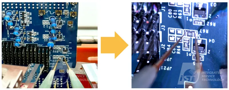
- Access to Dense Boards: As PCB designs become more compact, flying probes can access tight spaces and test points as small as 0.2mm apart, ensuring thorough testing even on high-density boards.
These advantages make flying probe testing a powerful tool for manufacturers looking to maintain high quality without sacrificing efficiency.
Limitations of Flying Probe Testing: What to Keep in Mind
While flying probe testing is highly effective, it’s not without its challenges. Understanding these limitations can help manufacturers decide when to use this method for flying probe testing components.
- Slower Testing Speed: Because the probes move sequentially from one test point to another, flying probe testing is slower than ICT for high-volume production. A single board with 500 test points might take several minutes to complete.
- Limited Power Testing: Flying probe testers are not suited for functional testing under full power conditions, as they focus on low-voltage electrical checks. Additional testing methods may be needed for power-intensive applications.
- Component Accessibility: While flying probes can reach most test points, components placed under shields or in hard-to-reach areas may still pose challenges.
Despite these limitations, flying probe testing remains a top choice for detailed diagnostics, especially in early-stage production and complex designs.
Applications of Flying Probe Testing in Modern Electronics
Flying probe testing plays a vital role in various stages of electronics manufacturing. Here are some common applications where it excels in PCB component testing:
- Prototype Validation: For new designs, flying probe testing ensures that every component, from resistors to capacitors, functions as expected before moving to mass production.
- Low-Volume Production: Small batches of PCBs benefit from the cost savings of fixtureless testing, avoiding the expense of custom fixtures.
- High-Mix Environments: In facilities producing a variety of PCB designs, flying probe testing offers the flexibility to switch between different layouts without downtime.
- Failure Analysis: When a board fails, flying probe testing can isolate the faulty component, whether it’s a resistor reading 50kΩ instead of 5kΩ or a capacitor with excessive leakage.
These applications highlight the versatility of flying probe testing in maintaining quality across diverse manufacturing needs.
Best Practices for Effective Flying Probe Testing
To maximize the benefits of flying probe testing for flying probe testing components, manufacturers should follow these best practices:
- Optimize Test Point Design: Ensure that test points are accessible and clearly defined in the PCB layout. Pads should be at least 0.5mm in diameter for reliable probe contact.
- Update Netlist Data: Always use the latest design files to program the tester, avoiding mismatches between the expected and actual board layout.
- Combine Testing Methods: For comprehensive quality assurance, pair flying probe testing with other methods like automated optical inspection (AOI) to cover visual and functional defects.
- Maintain Equipment: Regularly calibrate and maintain the flying probe tester to ensure measurement accuracy, especially for precise readings like resistance down to 0.01 ohms.
Following these practices ensures that flying probe testing delivers consistent, reliable results for every PCB.
Conclusion: Elevating PCB Quality with Flying Probe Testing
Flying probe testing has revolutionized the way manufacturers approach PCB component testing, offering a flexible, accurate, and cost-effective solution for diagnosing issues at the component level. Whether it’s flying probe testing resistor values to ensure proper resistance or conducting flying probe testing capacitor checks to verify charge storage, this method provides the precision needed to catch faults early and maintain high-quality standards.
For engineers and manufacturers, adopting flying probe testing means fewer defective boards, reduced production costs, and faster time-to-market, especially for prototypes and small runs. By understanding how this technology works and leveraging its strengths, you can elevate the reliability of your PCBs and deliver superior products to your customers. At ALLPCB, we’re committed to providing cutting-edge solutions for all your PCB testing and manufacturing needs, ensuring every board meets the highest standards of performance.


