 ALLPCB


If you're an electrical engineer working on engine control units (ECUs) in the automotive industry, you know that heat dissipation is a critical challenge. High-performance ECU PCBs (Printed Circuit Boards) operate under intense conditions, managing complex computations for engine performance, emissions control, and safety systems. Without proper thermal management, excessive heat can degrade components, reduce reliability, and even cause system failures. So, how do you tackle this issue? In this blog, we’ll explore effective thermal management strategies for ECU PCB heat dissipation, including thermal vias for engine control units, PCB cooling techniques for automotive applications, and high-temperature PCB materials for ECUs. Let’s dive into actionable solutions to keep your designs cool and reliable under pressure.
Why Thermal Management Matters for ECU PCBs
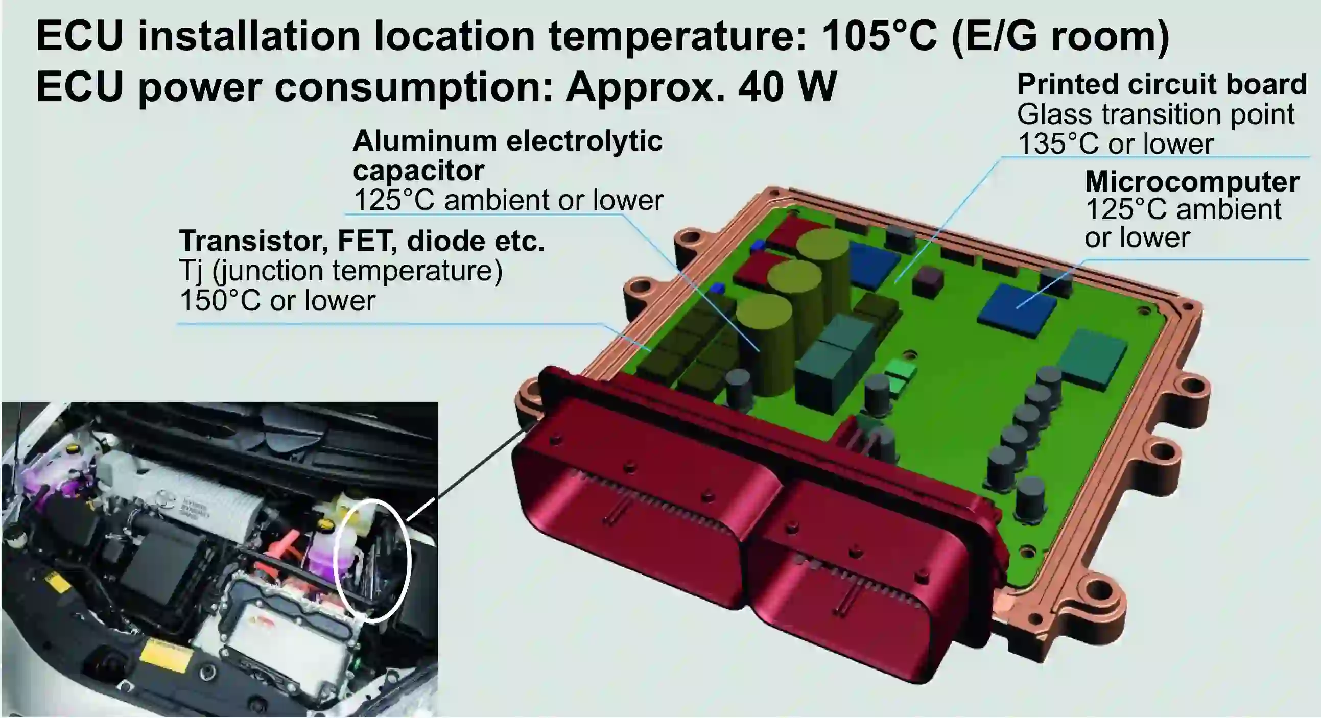
ECU PCBs are the brain of modern vehicles, controlling everything from fuel injection to traction control. These boards often operate in harsh environments—think under-the-hood temperatures exceeding 125°C in some cases, combined with high current loads and densely packed components. Without effective heat dissipation, hotspots can form, leading to thermal stress, reduced lifespan of components like microcontrollers and power transistors, and potential safety risks.
Effective thermal management isn’t just about preventing failure; it’s about ensuring consistent performance. For instance, a study in automotive electronics found that every 10°C increase in operating temperature can halve the lifespan of certain components. That’s why engineers must prioritize strategies to manage heat in high-performance ECU designs. Let’s break down the key approaches to achieve this.
Key Thermal Management Strategies for ECU PCBs
1. Leveraging Thermal Vias for Engine Control Units
One of the most effective ways to manage heat in ECU PCBs is through the use of thermal vias. These are small, copper-filled holes strategically placed in the PCB to transfer heat from high-temperature components to a heat sink or other cooling layers. Thermal vias act like thermal highways, pulling heat away from critical areas and spreading it across the board or to an external cooling mechanism.
For example, in a typical ECU design, power transistors or microcontrollers might generate significant heat—sometimes up to 5-10 watts per component. By placing thermal vias directly under these components, you can reduce junction temperatures by as much as 15-20°C, depending on the via density and board thickness. A common practice is to use a grid of vias with a diameter of 0.3-0.5 mm, spaced 1-2 mm apart, to maximize heat transfer without compromising structural integrity.
However, there are design considerations to keep in mind. Too many vias can weaken the PCB or interfere with signal routing. Additionally, thermal vias are most effective when paired with a copper plane or heat sink on the opposite side of the board. For automotive ECUs, where space is tight, engineers often combine thermal vias with multi-layer boards to optimize heat dissipation.
2. PCB Cooling Techniques for Automotive Applications
Beyond thermal vias, there are several PCB cooling techniques tailored for automotive environments that can significantly enhance thermal performance. Let’s explore a few practical methods:
- Copper Planes and Traces: Increasing the copper thickness in critical areas of the PCB can improve heat spreading. For instance, using 2 oz or 3 oz copper (instead of the standard 1 oz) for power traces can reduce thermal resistance by up to 30%. Wider traces also help distribute heat more evenly across the board.
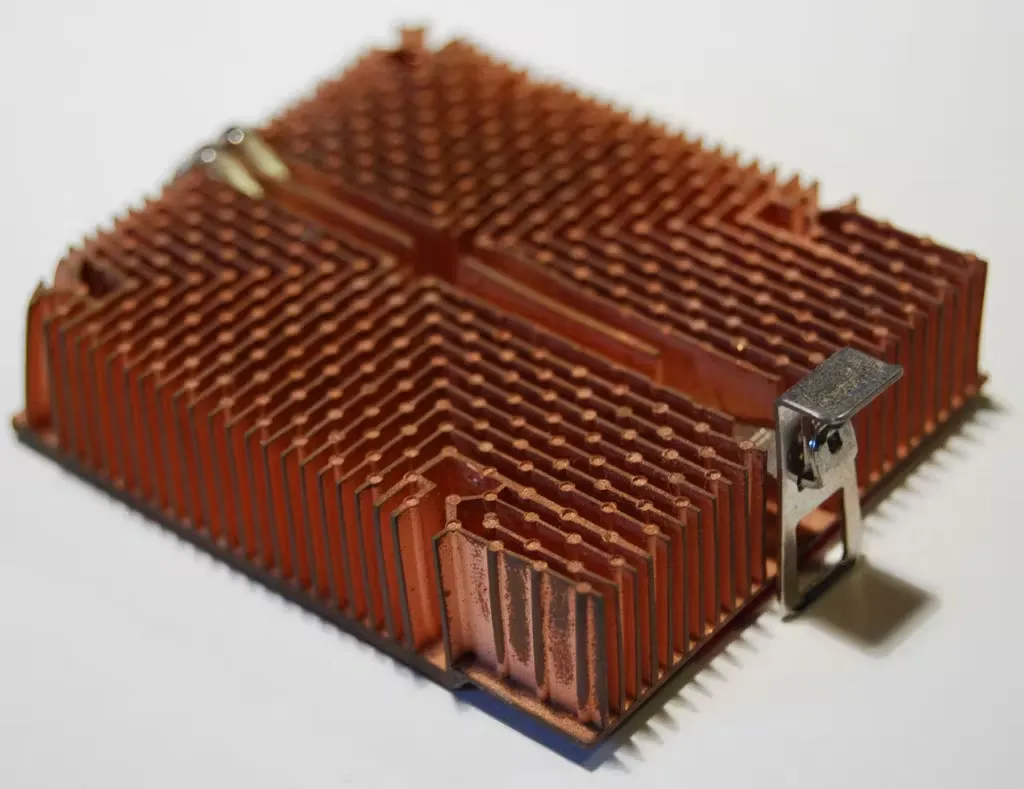
- Heat Sinks and Thermal Pads: Attaching heat sinks directly to high-power components like voltage regulators or MOSFETs is a tried-and-true method. Thermal pads or interface materials with high thermal conductivity (e.g., 3-5 W/m·K) ensure efficient heat transfer from the component to the sink. In ECU designs, compact heat sinks are often used due to space constraints.
- Active Cooling with Fans: While less common in under-the-hood ECUs due to environmental challenges, active cooling with small fans or blowers can be used in less harsh areas of the vehicle. This method is more effective for high-performance ECUs in electric vehicles (EVs) where heat loads are extreme—sometimes exceeding 50 watts per board.
- Board Layout Optimization: Strategic placement of components can minimize heat buildup. For example, spacing out heat-generating components and placing them near board edges or ventilation areas can reduce localized hotspots. Simulation tools like ANSYS or Altium’s thermal analysis features can predict heat distribution and guide layout decisions.
These techniques, when combined, can lower PCB temperatures by 10-30°C, depending on the design and operating conditions. For automotive applications, where reliability is non-negotiable, using a mix of passive and active cooling methods tailored to the specific ECU’s environment is often the best approach.
3. High-Temperature PCB Materials for ECUs
The choice of PCB material plays a huge role in PCB thermal management. Standard FR-4 materials, while cost-effective, often struggle in the high-temperature environments of automotive ECUs, where temperatures can range from -40°C to 150°C. FR-4 typically has a glass transition temperature (Tg) of around 130-140°C, meaning it can soften or degrade under extreme heat, leading to mechanical and electrical failures.
For high-performance ECUs, engineers often turn to advanced materials with better thermal properties:
- High-Tg FR-4: With a Tg of 170-180°C, high-Tg FR-4 offers better heat resistance than standard FR-4. It’s a budget-friendly upgrade for ECUs operating in moderately high temperatures.
- Polyimide: Polyimide materials can withstand temperatures up to 250°C and are highly resistant to thermal cycling. They’re ideal for ECUs in extreme environments, though they come at a higher cost and can be harder to process.
- Ceramic-Based Materials: Materials like aluminum oxide or aluminum nitride provide exceptional thermal conductivity (up to 170 W/m·K for aluminum nitride) compared to FR-4 (0.3 W/m·K). These are often used in hybrid ECUs or power modules where heat dissipation is critical.
- Metal-Core PCBs (MCPCBs): MCPCBs feature a metal base layer (usually aluminum or copper) that acts as a built-in heat sink. They’re particularly effective for ECU designs with high-power components, as they can reduce thermal resistance by up to 50% compared to traditional PCBs.
Choosing the right material depends on factors like cost, thermal requirements, and manufacturing constraints. For instance, while ceramic materials excel in heat dissipation, their brittleness and high cost may limit their use to specific high-end applications. On the other hand, MCPCBs strike a balance between performance and practicality for many automotive ECUs.
Advanced Thermal Management: Simulation and Testing
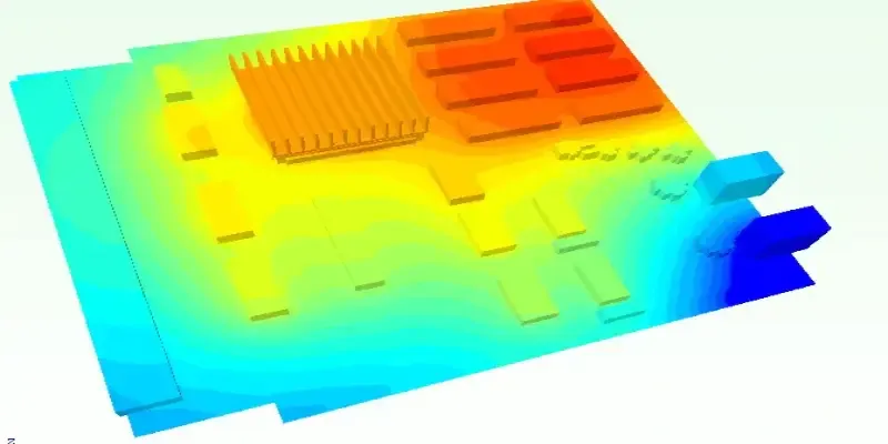
Designing for thermal performance isn’t just about choosing the right materials or techniques—it’s also about validation. Thermal simulation tools are invaluable for predicting how an ECU PCB will behave under real-world conditions. Tools like COMSOL Multiphysics or Mentor Graphics’ FloTHERM allow engineers to model heat flow, identify potential hotspots, and test different cooling strategies before prototyping.
For example, a simulation might reveal that a specific MOSFET reaches a junction temperature of 150°C under full load, exceeding its safe operating limit of 125°C. Armed with this data, you can adjust the design—perhaps by adding more thermal vias or increasing copper thickness—before building a physical board.
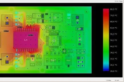
Once a prototype is built, real-world testing is crucial. Using thermal cameras or thermocouples, you can measure actual temperatures across the PCB and compare them to simulation results. This iterative process ensures that your thermal management strategy is both effective and reliable. In my own experience working on automotive projects, I’ve found that combining simulation with testing often uncovers small but critical issues, like insufficient thermal paste coverage under a heat sink, that can make a big difference in performance.
Challenges and Considerations in ECU Thermal Management
While the strategies above are effective, implementing them in automotive ECUs comes with unique challenges. Space constraints often limit the size of heat sinks or the number of layers in a PCB. Cost is another factor—high-temperature materials like polyimide or ceramic can significantly increase production expenses. Additionally, automotive standards like ISO 16750 demand that ECUs withstand thermal cycling, vibration, and humidity, which can complicate cooling designs.
Balancing thermal performance with these constraints requires creativity and compromise. For instance, in one project I worked on, we couldn’t afford a full MCPCB due to budget limits, so we opted for a hybrid design with localized metal inserts under high-power components. This approach cut costs while still improving heat dissipation by about 25% compared to a standard FR-4 board.
Future Trends in ECU PCB Thermal Management
As vehicles become more electrified and autonomous, the demand for high-performance ECUs will only grow, along with the need for advanced thermal management. Emerging trends include:
- Liquid Cooling: Some high-end electric vehicle ECUs are adopting liquid cooling systems, where coolant channels are integrated into the PCB or enclosure, offering superior heat removal compared to air cooling.
- Advanced Thermal Interface Materials (TIMs): New TIMs with thermal conductivities exceeding 10 W/m·K are being developed, promising better heat transfer between components and heat sinks.
- 3D PCB Designs: Stacking components in 3D configurations can optimize space, but it also introduces new thermal challenges. Innovative designs with embedded cooling channels are being explored to address this.
Staying ahead of these trends can give engineers a competitive edge in designing next-generation ECUs that handle higher power densities without sacrificing reliability.
Conclusion: Building Cooler, More Reliable ECU PCBs
Thermal management is a cornerstone of high-performance ECU PCB design. By leveraging strategies like thermal vias for engine control units, applying PCB cooling techniques for automotive applications, and selecting high-temperature PCB materials for ECUs, engineers can ensure their designs operate reliably even in the harshest conditions. Tools like thermal simulation and real-world testing further refine these solutions, helping to catch issues before they become problems.
Whether you’re working on a traditional internal combustion engine ECU or a cutting-edge electric vehicle controller, the principles of heat dissipation remain the same: anticipate heat sources, design for efficient transfer, and validate your approach.
By focusing on ECU PCB heat dissipation and staying informed about new techniques and materials, you can build systems that not only meet today’s demands but also pave the way for tomorrow’s innovations in automotive electronics.


