 ALLPCB


Designing a PCB for air quality monitoring systems is a critical task that directly impacts sensor accuracy and data reliability. Whether you're working with sensors like the BME680, PMS5003, or MQ135, a well-thought-out PCB layout can make the difference between precise readings and noisy, unreliable data. In this comprehensive guide, we'll explore the best practices for air quality sensor PCB layout, sensor placement for accurate readings, and minimizing noise in air quality PCB designs. We'll dive into specific design tips for the BME680, PMS5003, and MQ135 sensors to help you achieve optimal performance in your projects.
Why PCB Design Matters for Air Quality Monitoring
Air quality monitoring systems are essential for applications ranging from environmental studies to smart home devices. These systems rely on sensors to detect parameters like particulate matter (PM), volatile organic compounds (VOCs), and gas concentrations. However, even the most advanced sensors can produce inaccurate results if the PCB design introduces noise, interference, or poor signal integrity. A carefully optimized PCB layout ensures that sensors operate at their full potential by reducing electrical noise, maintaining stable power delivery, and providing proper grounding.
In the following sections, we'll break down the key aspects of air quality sensor PCB layout, offering actionable advice for engineers looking to enhance sensor accuracy and reliability.
Key Principles of Air Quality Sensor PCB Layout
Creating an effective PCB layout for air quality monitoring starts with understanding the fundamental principles of design. These principles focus on minimizing interference, ensuring proper sensor placement, and optimizing signal paths. Let's explore these in detail.
1. Sensor Placement for Accurate Readings
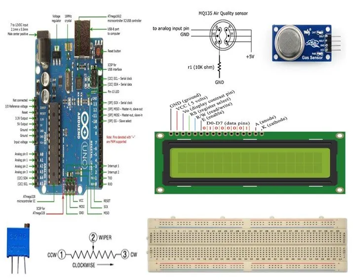
Proper sensor placement is crucial for obtaining accurate data. Sensors like the BME680 (which measures temperature, humidity, pressure, and VOCs), PMS5003 (a particulate matter sensor), and MQ135 (a gas sensor for detecting air pollutants) are sensitive to their physical environment. Incorrect placement can lead to interference from heat sources, airflow disruptions, or electromagnetic noise.
- Isolate Sensors from Heat Sources: Place sensors away from components that generate heat, such as power regulators or microcontrollers. For example, the BME680's temperature readings can be skewed if it's near a hot IC. Maintain a distance of at least 10-15 mm from high-power components.
- Optimize Airflow for Gas and PM Sensors: For sensors like the PMS5003 and MQ135, ensure they are positioned in areas with unobstructed airflow. Avoid placing them near enclosure walls or other components that could block air intake. If possible, use cutouts or vents in the PCB or enclosure design to facilitate air movement.
- Avoid Electromagnetic Interference (EMI): Keep sensors away from high-frequency signal traces or switching power supplies. For instance, routing high-speed digital signals near the BME680 can introduce noise into its sensitive analog outputs.
2. Minimizing Noise in Air Quality PCB Designs
Electrical noise is one of the biggest challenges in air quality monitoring systems. Noise can distort sensor readings, leading to inaccurate data. Here are some strategies to minimize noise in your PCB design:
- Use Ground Planes: Implement a solid ground plane beneath the sensor area to provide a low-impedance path for return currents. This helps reduce EMI and crosstalk. For a 4-layer PCB, dedicate one layer to ground to separate signal layers and minimize interference.
- Decouple Power Supply Lines: Place decoupling capacitors (e.g., 0.1 μF and 1 μF) close to the power pins of each sensor. For the BME680, which operates at 1.8V to 3.6V, a clean power supply is critical to avoid noise in its gas sensor readings.
- Shorten Signal Traces: Keep analog and digital signal traces as short as possible to reduce the chance of picking up noise. Route sensitive traces, such as those from the MQ135's analog output, away from high-speed digital lines.
- Separate Analog and Digital Domains: If your design includes both analog (sensor outputs) and digital (microcontroller) components, separate these domains on the PCB. Use different ground planes for analog and digital sections, connected at a single point to avoid ground loops.
Specific PCB Design Tips for Popular Air Quality Sensors
Each air quality sensor has unique characteristics and requirements that influence PCB design. Below, we'll cover tailored design tips for the BME680, PMS5003, and MQ135 sensors to ensure optimal performance.
PCB Design for BME680 Sensor
The BME680 is a versatile environmental sensor that measures temperature, humidity, pressure, and gas (VOCs). Its small size and low power consumption make it ideal for compact air quality monitoring devices, but its sensitivity requires careful PCB design.
- Power Supply Stability: The BME680 operates within a voltage range of 1.8V to 3.6V and draws a current of about 3.7 mA during gas measurements. Use a low-noise LDO regulator to supply power and place a 0.1 μF capacitor within 2 mm of the VDD pin to filter out high-frequency noise.
- Thermal Isolation: Since the BME680 includes a gas sensor that heats up during measurements (up to 320°C internally for brief periods), avoid placing it near other heat-sensitive components. Ensure thermal vias or cutouts if heat dissipation is a concern.
- Signal Integrity: The BME680 communicates via I2C or SPI protocols. Keep clock and data lines short (less than 10 cm) and route them away from power traces to prevent crosstalk. If using I2C, add pull-up resistors (typically 4.7 kΩ) close to the sensor.
PCB Design for PMS5003 Sensor
The PMS5003 is a particulate matter sensor widely used for detecting PM1.0, PM2.5, and PM10 concentrations. It uses a laser scattering principle, making its placement and electrical environment critical for accurate readings.
- Airflow Considerations: The PMS5003 requires a consistent airflow through its inlet and outlet to measure particulate matter accurately. Mount the sensor in a location where air can flow freely, and avoid placing it near components that could create turbulence or block the air path.
- Power Requirements: This sensor operates at 5V and can draw up to 100 mA during operation. Ensure the power trace can handle this current without significant voltage drops. Place a 10 μF capacitor near the power pin to stabilize the supply during peak current draws.
- Digital Communication: The PMS5003 uses a UART interface for data transmission. Route the TX and RX lines away from noisy areas of the PCB, and consider adding a small series resistor (e.g., 22 Ω) on these lines to reduce ringing.
PCB Design for MQ135 Sensor
The MQ135 is a low-cost gas sensor used to detect air pollutants like ammonia, benzene, and carbon dioxide. Its analog output is highly sensitive to electrical noise, so PCB design must prioritize signal integrity.
- Analog Output Protection: The MQ135 outputs an analog voltage proportional to gas concentration. Route this signal trace on an inner layer if possible, shielded by ground planes, to minimize noise pickup. Avoid running it parallel to digital or power traces for more than 5 mm.
- Heater Circuit Design: The MQ135 has a built-in heater that requires a stable 5V supply drawing around 150 mA. Use wide traces (at least 20 mils) for the heater circuit to handle the current, and place a 1 μF capacitor near the heater pin to smooth out voltage fluctuations.
- Calibration Environment: Since the MQ135 is sensitive to environmental factors, ensure its placement allows for calibration in a controlled setting. Avoid mounting it near sources of vibration or rapid temperature changes that could affect readings.
Advanced Techniques for Enhancing Sensor Accuracy
Beyond basic layout and placement, advanced techniques can further improve the performance of air quality monitoring systems. These methods focus on fine-tuning the electrical and physical environment of the PCB.
1. Use of Shielding and Filtering
For high-accuracy applications, consider adding shielding around sensitive sensors to block external EMI. A grounded metal shield or enclosure can protect sensors like the MQ135 from interference. Additionally, use low-pass filters on analog outputs to remove high-frequency noise. For instance, a simple RC filter with a 1 kΩ resistor and a 0.1 μF capacitor can smooth out fluctuations in the MQ135's output signal.
2. Impedance Matching for High-Frequency Signals
If your design includes high-frequency communication (e.g., SPI at 10 MHz for the BME680), ensure proper impedance matching for signal traces. Maintain a characteristic impedance of 50 Ω for these lines by adjusting trace width and spacing based on your PCB stack-up. This reduces signal reflections and ensures clean data transmission.
3. Thermal Management
Sensors like the BME680 and MQ135 generate heat during operation, which can affect nearby components or even their own readings. Incorporate thermal vias under these sensors to dissipate heat into the ground plane. For multilayer PCBs, ensure a copper pour on the bottom layer acts as a heat sink.
Common Pitfalls to Avoid in Air Quality PCB Design
Even with careful planning, certain mistakes can compromise the accuracy of air quality sensors. Here are some common pitfalls and how to avoid them:
- Overcrowding the PCB: Placing components too close to sensors can lead to thermal and EMI issues. Maintain adequate spacing, especially around the PMS5003, which requires clear airflow.
- Ignoring Ground Loops: Multiple ground connections between analog and digital sections can create loops, introducing noise. Use a star grounding topology to connect all grounds at a single point.
- Neglecting Power Supply Noise: A noisy power supply can degrade sensor performance. Always use proper decoupling and consider a dedicated voltage regulator for sensitive sensors like the BME680.
Testing and Validation of Your PCB Design
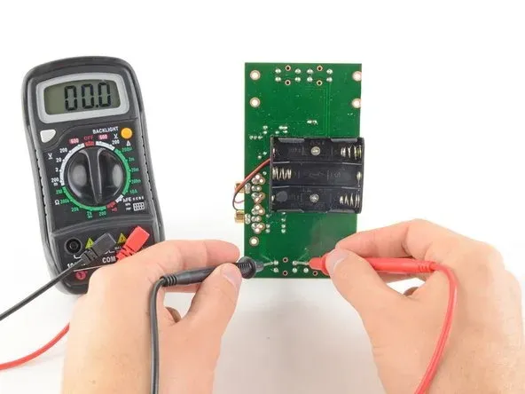
Once your PCB is assembled, thorough testing is essential to verify sensor accuracy. Use a calibrated reference device to compare your sensor readings under controlled conditions. For example, test the PMS5003 in a chamber with known PM2.5 concentrations to ensure its readings are within ±10% of the reference. Similarly, expose the MQ135 to known gas concentrations to calibrate its output voltage. Document any discrepancies and adjust your design (e.g., adding filters or repositioning sensors) as needed.
Conclusion: Building Better Air Quality Monitoring Systems
Optimizing PCB design for air quality monitoring is a multifaceted process that requires attention to sensor placement, noise reduction, and tailored design considerations for each sensor type. By following the guidelines outlined in this post—whether you're focusing on air quality sensor PCB layout, minimizing noise in air quality PCB, or designing for the BME680, PMS5003, or MQ135 sensors—you can significantly enhance the accuracy and reliability of your system.
Remember that every detail, from grounding techniques to thermal management, plays a role in the performance of your air quality monitoring device. With a well-designed PCB, you can ensure that your sensors deliver precise data, helping to create safer and healthier environments through effective air quality monitoring.


