 ALLPCB


Are you a hobbyist working on PCB projects at home and struggling with overheating components? If so, learning how to implement DIY thermal vias can be a game-changer for your designs. Thermal vias are small, conductive holes in a printed circuit board (PCB) that help transfer heat away from hot components to a cooler area, like a ground plane or heat sink. In this guide, we’ll walk you through the basics of using thermal vias in hobbyist PCB projects, offering simple steps for home PCB design and beginner thermal management. Whether you’re new to electronics or looking for simple PCB cooling solutions, this post will help you keep your circuits running smoothly.
Let’s dive into the details of why thermal vias matter, how they work, and how you can add them to your next project with minimal tools and experience. By the end of this guide, you’ll have a clear understanding of thermal management and practical tips to apply in your own designs.
Why Thermal Management Matters in Hobbyist PCB Projects
Heat is a common enemy in electronics. When components like microcontrollers, power regulators, or LEDs get too hot, they can fail prematurely or behave unpredictably. For hobbyists working on small-scale projects at home, overheating can turn a promising design into a frustrating mess. This is where beginner thermal management comes into play. Managing heat ensures your components last longer, perform better, and stay safe.
In a typical PCB, heat builds up in areas with high power dissipation. Without proper cooling, temperatures can rise above safe limits—often exceeding 85°C for many components, leading to thermal stress or failure. Thermal vias offer a low-cost, effective way to tackle this issue by creating pathways for heat to escape. They’re especially useful in hobbyist PCB projects where advanced cooling solutions like active fans or large heat sinks might not be practical or affordable.
What Are Thermal Vias and How Do They Work?
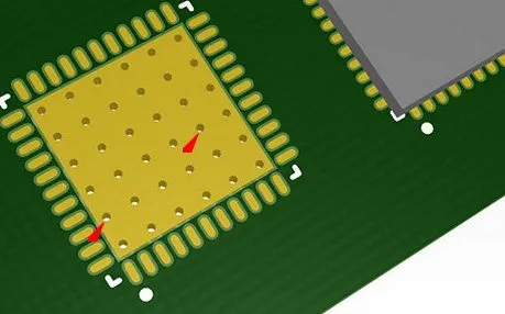
Thermal vias are small holes drilled into a PCB and filled or plated with a conductive material, usually copper. These vias connect the top layer of the board—where heat-generating components sit—to a lower layer or ground plane that can absorb or spread the heat. Think of them as tiny heat pipes that move thermal energy away from sensitive areas.
The principle is simple: heat flows from hot to cold. A thermal via provides a low-resistance path for heat to travel, reducing the temperature of the component above it. For example, if a power IC on your board reaches 100°C, a set of thermal vias can transfer heat to a copper ground plane, potentially dropping the IC’s temperature by 10-20°C, depending on the design and materials. This is a critical step in simple PCB cooling for home projects.
Unlike regular vias used for electrical connections, thermal vias are often placed in arrays under or around components with high heat output. They don’t always carry signals; their main job is heat dissipation. This makes them a perfect tool for DIY thermal vias in beginner designs.
Benefits of Using Thermal Vias in Home PCB Design
Adding thermal vias to your home PCB design offers several advantages, especially for hobbyists on a budget or with limited resources. Here are some key benefits:
- Cost-Effective Cooling: Thermal vias are cheaper than adding external heat sinks or fans. They use the existing layers of your PCB to manage heat.
- Space-Saving: For small projects, where every millimeter counts, thermal vias take up no extra space beyond the board itself.
- Improved Reliability: Lowering component temperatures can extend the lifespan of your electronics, preventing failures during long-term use.
- Beginner-Friendly: With basic design software and manufacturing options, even new hobbyists can implement thermal vias without advanced skills.
By incorporating thermal vias, you’re not just solving a heat problem—you’re building more robust and efficient circuits for your hobbyist PCB projects.
Tools and Materials for DIY Thermal Vias
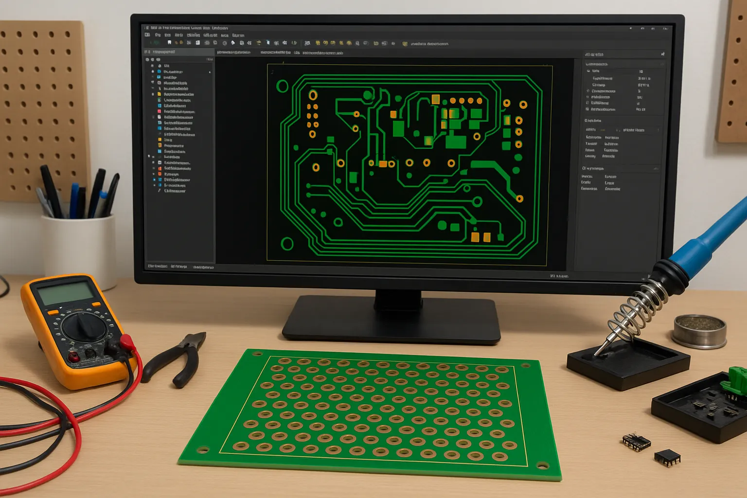
Before you start adding thermal vias to your PCB, gather the necessary tools and materials. As a hobbyist, you likely already have some of these on hand. Here’s what you’ll need for home PCB design with thermal vias:
- PCB Design Software: Use free or affordable software to design your board and place thermal vias. Popular options include tools that allow you to define via sizes and patterns easily.
- PCB Board: Whether you’re etching your own board at home or ordering a manufactured one, ensure it supports multiple layers (at least two) for effective heat transfer.
- Drill (Optional): If you’re making boards at home, a small drill can create via holes. Typical via diameters range from 0.3mm to 0.8mm for thermal purposes.
- Conductive Material: For home-etched boards, you might need copper wire or conductive epoxy to fill vias if plating isn’t an option.
For most hobbyists, ordering a professionally manufactured board is the easiest way to get thermal vias done right. Many services offer low-cost options for small runs, and they handle the via plating automatically based on your design files.
Step-by-Step Guide to Adding Thermal Vias in Hobbyist PCB Projects
Now that you understand the basics, let’s go through a practical guide to implementing DIY thermal vias in your next project. These steps are tailored for beginners and focus on simple PCB cooling techniques.
Step 1: Identify Heat-Generating Components
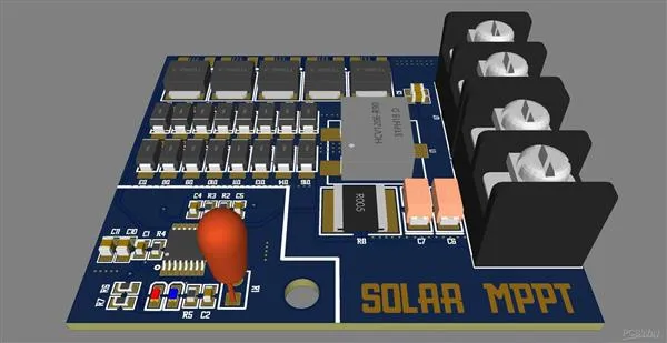
Start by looking at your circuit design and pinpointing components that produce the most heat. Common culprits include voltage regulators, power transistors, and high-current LEDs. Check datasheets for these components to find their maximum operating temperature (often between 85°C and 125°C) and power dissipation ratings (e.g., 1W or higher).
Step 2: Plan Thermal Via Placement
In your PCB design software, place thermal vias directly under or around the heat-generating component. A common practice is to arrange 4-8 vias in a grid pattern beneath the component’s thermal pad. Keep via diameters small (around 0.3-0.5mm) to fit more in a tight space, and space them about 1-2mm apart for optimal heat transfer without weakening the board structure.
Step 3: Connect Vias to a Ground Plane or Copper Layer
Ensure the vias connect to a large copper area, like a ground plane on the bottom layer of your PCB. This copper acts as a heat sink, spreading thermal energy across a wider surface. If your board is single-sided, add a large copper pour on the same side and link the vias to it.
Step 4: Verify Design Rules
Before finalizing your design, check that your thermal vias meet manufacturing constraints. Most PCB fabrication services have minimum via sizes and spacing requirements. For hobbyist boards, sticking to standard sizes (like 0.4mm diameter) ensures compatibility and keeps costs low.
Step 5: Test and Monitor After Assembly
Once your board is assembled, power it up and monitor temperatures using a thermal camera or infrared thermometer if available. Look for hot spots above 80°C, which might indicate the need for more vias or a different placement. If temperatures are still high, consider adding a small heat sink in addition to the vias.
Common Mistakes to Avoid in Beginner Thermal Management
While thermal vias are a straightforward solution, beginners often make mistakes that reduce their effectiveness. Here are some pitfalls to watch out for in hobbyist PCB projects:
- Too Few Vias: Placing just one or two vias won’t transfer enough heat. Aim for a small array (4-12 vias) under high-heat components.
- Poor Connection to Copper: If vias aren’t properly linked to a large copper plane, heat won’t dissipate effectively. Always connect to a ground or power plane.
- Ignoring Board Thickness: Thicker boards (above 1.6mm) reduce the efficiency of thermal vias because heat has to travel farther. Stick to standard 1.6mm boards for best results.
- Overloading Small Boards: If your design has multiple heat sources in a small area, thermal vias alone might not be enough. Combine them with other cooling methods like copper pours or small heat sinks.
By avoiding these errors, you’ll maximize the impact of your DIY thermal vias and keep your components cool.
Additional Tips for Simple PCB Cooling at Home
Beyond thermal vias, there are other easy ways to enhance cooling in home PCB design. These tips complement your thermal via strategy and are perfect for hobbyists:
- Use Larger Copper Areas: Maximize copper pours on your board to act as passive heat sinks. A copper area of 5cm2 can significantly lower temperatures around a component dissipating 1W of heat.
- Optimize Component Placement: Space out heat-generating components to avoid concentrated hot spots. Leave at least 5-10mm between high-power parts if possible.
- Add Ventilation Holes: If your project is enclosed, drill small holes in the enclosure for airflow. This passive cooling method works well with thermal vias.
- Choose the Right Board Material: Standard FR-4 boards handle moderate heat, but for high-power projects, consider materials with better thermal conductivity if your budget allows.
These small adjustments can make a big difference in simple PCB cooling and overall project success.
When to Seek Professional Help for Thermal Management
While DIY thermal vias are great for many hobbyist projects, some designs might need more advanced solutions. If you’re working on a high-power circuit (dissipating over 5W) or notice persistent overheating despite adding vias, it might be time to consult a professional or upgrade to more sophisticated cooling methods. Complex multilayer boards, active cooling systems, or specialized materials can address extreme heat issues that go beyond beginner techniques.
For most hobbyists, though, thermal vias and basic design tweaks will handle 80-90% of thermal challenges without extra cost or complexity.
Conclusion: Mastering DIY Thermal Vias for Better PCB Designs
Thermal vias are a powerful yet simple tool for managing heat in hobbyist PCB projects. By understanding how they work and following the steps outlined in this guide, you can implement DIY thermal vias in your home PCB design with confidence. From identifying hot components to placing vias effectively, these beginner thermal management techniques offer a practical way to achieve simple PCB cooling without breaking the bank.
Start small with your next project—add a few thermal vias under a power-hungry component and monitor the difference. As you gain experience, you’ll find new ways to optimize heat dissipation and build more reliable circuits. With the right approach, overheating will no longer hold back your creative ideas, letting you focus on innovation and experimentation in your electronics journey.


