 ALLPCB


Designing a printed circuit board (PCB) for a defibrillator can seem daunting, especially for beginners. However, with the right guidance and a clear step-by-step approach, you can create a functional and safe PCB layout for medical devices like defibrillators. In this comprehensive guide, we’ll walk you through the essentials of defibrillator PCB design, from understanding high voltage requirements to selecting components and using PCB design software for beginners. Whether you're looking for a defibrillator PCB design tutorial or tips on basic PCB layout for medical devices, this post will provide actionable insights to help you succeed.
Why Defibrillator PCB Design Matters
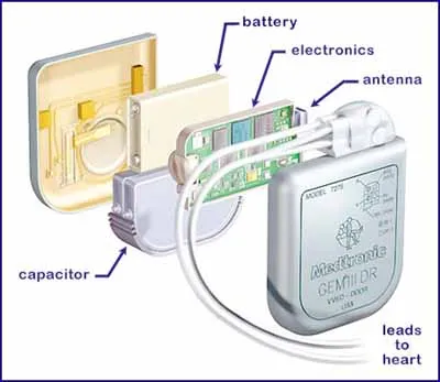
Defibrillators are life-saving medical devices that deliver controlled electric shocks to restore normal heart rhythm during cardiac arrest. The PCB inside a defibrillator is the heart of the device, managing high voltage circuits, signal processing, and safety features. A poorly designed PCB can lead to device failure, safety risks, or unreliable performance. That’s why mastering defibrillator PCB design is crucial for engineers working on medical devices.
In this blog, we’ll break down the process into manageable steps, focusing on high voltage design principles, component selection, and layout tips tailored for beginners. Let’s dive into the details of creating a safe and effective PCB for a defibrillator.
What You’ll Learn in This Guide
- Basics of defibrillator PCB design and its unique challenges.
- Step-by-step process for designing a PCB layout for medical devices.
- Tips for selecting components for defibrillator PCBs.
- Understanding high voltage design and safety considerations.
- Using PCB design software for beginners to streamline the process.
Step 1: Understanding the Basics of Defibrillator PCB Design
Before starting your design, it’s important to understand what makes defibrillator PCBs unique. These boards handle extremely high voltages—often between 1,000 to 2,000 volts—to deliver the necessary shock. They also include low-voltage circuits for control, monitoring, and user interface. Balancing these two aspects while ensuring safety and reliability is the core challenge of defibrillator PCB design.
Key considerations include:
- High Voltage Handling: Circuits must withstand high voltage without arcing or breakdown. This requires wide trace spacing and specialized materials.
- Safety Standards: Medical devices must comply with strict regulations like IEC 60601-1, which covers electrical safety and performance.
- Signal Integrity: Low-voltage control circuits must operate without interference from high-voltage components.
- Compact Design: Defibrillators, especially portable ones, need compact layouts to fit into small enclosures.
For beginners, starting with a clear understanding of these requirements will guide every decision in the design process, from component selection to layout planning.
Step 2: Choosing the Right PCB Design Software for Beginners
Selecting user-friendly PCB design software is a critical first step for beginners. The right tool simplifies the design process, offers built-in libraries for components, and helps ensure your layout meets industry standards. While there are many options available, look for software that offers a balance of simplicity and advanced features for medical device design.
Key features to look for in PCB design software for beginners include:
- Intuitive schematic editor for creating circuit diagrams.
- Extensive component libraries, including high-voltage capacitors and resistors.
- Design rule checks (DRC) to catch errors like insufficient spacing for high-voltage traces.
- 3D visualization to preview how your PCB fits into the defibrillator enclosure.
Start by practicing with simple designs to get comfortable with the software before tackling a complex defibrillator PCB. Many tools also offer tutorials and community support, which are invaluable for beginners.
Step 3: Selecting Components for Defibrillator PCBs
Component selection is a foundational step in defibrillator PCB design. The wrong components can lead to circuit failure, safety hazards, or inefficient performance. When selecting components for defibrillator PCBs, prioritize reliability, voltage ratings, and compliance with medical standards.
Key Components for Defibrillator PCBs
- High-Voltage Capacitors: These store the energy needed for the shock. Choose capacitors rated for at least 2,000 volts with low leakage current. For example, a 100 μF capacitor rated at 2,500 volts is often used in automated external defibrillators (AEDs).
- Power Transistors or IGBTs: Insulated Gate Bipolar Transistors (IGBTs) are commonly used to switch high voltages. Select components with a voltage rating 20-30% higher than your design’s maximum to ensure safety.
- Transformers: Step-up transformers are used to generate high voltages. Ensure they have proper insulation to prevent arcing.
- Microcontrollers: For control and monitoring, choose a microcontroller with enough processing power to handle real-time tasks like heart rhythm analysis.
- Resistors and Diodes: Use high-voltage resistors and fast-recovery diodes to manage energy discharge and prevent reverse currents.
Always check datasheets for temperature ratings, as defibrillators may operate in varied environments. Additionally, source components from reputable suppliers to avoid counterfeits that could compromise safety.
Step 4: Understanding High Voltage Design Principles
High voltage design is the most critical aspect of a defibrillator PCB. Mishandling high voltage can lead to arcing, insulation breakdown, or even device failure during a critical moment. Here are the key principles to follow for safe and effective high voltage design:
- Trace Spacing and Clearance: Maintain adequate spacing between high-voltage traces to prevent arcing. For 1,500 volts, a clearance of at least 6 mm is recommended on the PCB surface, based on IEC standards.
- Creepage Distance: This is the shortest path along the PCB surface between two conductive parts. For high-voltage designs, a creepage distance of 8 mm or more may be required, depending on the voltage and environment.
- Insulation Materials: Use PCB substrates with high dielectric strength, such as FR-4 with enhanced insulation or specialized materials for medical applications.
- Ground Planes: Separate high-voltage and low-voltage ground planes to minimize interference and ensure signal integrity in control circuits.
Additionally, consider adding protective components like varistors or transient voltage suppressors to safeguard against voltage spikes. High voltage design requires precision, so always double-check your calculations and use design rule checks in your software.
Step 5: Creating a Basic PCB Layout for Medical Devices
Once you’ve selected components and understood high voltage requirements, it’s time to create your PCB layout. A well-designed layout ensures the defibrillator operates reliably and safely. Follow these steps for a basic PCB layout tailored to medical devices:
1. Start with a Schematic
Draw a schematic diagram that shows how components connect. Group high-voltage and low-voltage sections separately to avoid interference. Use your PCB design software to create this diagram, ensuring every connection is clearly labeled.
2. Place Components Strategically
Place high-voltage components like capacitors and transformers away from sensitive low-voltage circuits. Keep heat-generating components near the edges for better heat dissipation. For example, position the microcontroller centrally to minimize signal delays, which can be as low as 10 nanoseconds for critical operations.
3. Route High-Voltage Traces First
Route high-voltage traces with wide spacing (e.g., 0.5 mm or more for 1,500 volts) and avoid sharp corners to reduce the risk of arcing. Use thicker traces (e.g., 2 oz copper) for high-current paths to handle the energy discharge.
4. Add Ground and Power Planes
Use dedicated ground planes to reduce noise and improve stability. Separate power planes for high-voltage and low-voltage sections to prevent cross-talk. Ensure vias are placed strategically to connect layers without compromising insulation.
5. Test Your Layout with Design Rule Checks
Run design rule checks in your software to identify errors like insufficient clearance or overlapping traces. Fix any issues before moving to prototyping.
A well-thought-out PCB layout for medical devices like defibrillators prioritizes safety, functionality, and compactness. Take your time with this step, as errors in layout can be costly to fix later.

Step 6: Prototyping and Testing Your Defibrillator PCB
After completing your design, the next step is prototyping and testing. This ensures your PCB performs as expected under real-world conditions. Here’s how to approach this phase:
- Prototype Fabrication: Send your design files to a reliable manufacturing service to create a prototype. Ensure the manufacturer understands the high-voltage and medical device requirements.
- Visual Inspection: Check the prototype for soldering defects, component placement errors, or visible damage.
- Electrical Testing: Test for continuity, insulation resistance, and voltage withstand capability. For example, apply a test voltage of 2,000 volts to ensure no breakdown occurs in high-voltage sections.
- Functional Testing: Simulate the defibrillator’s operation to verify it delivers the correct energy output (e.g., 200 joules for an AED) and that control circuits function without interference.
Document any issues and revise your design as needed. Testing is critical for medical devices, as even small errors can have serious consequences.
Step 7: Ensuring Compliance with Medical Standards
Defibrillator PCBs must meet strict regulatory standards to ensure patient safety. Familiarize yourself with guidelines like IEC 60601-1, which specifies requirements for medical electrical equipment. Key compliance areas include:
- Electrical safety to prevent shocks or burns.
- Electromagnetic compatibility (EMC) to avoid interference with other devices.
- Reliability under varied environmental conditions, such as temperatures from 0°C to 40°C.
Work with a certification body to validate your design if you plan to bring the device to market. Compliance adds credibility and ensures your defibrillator is safe for use.
Tips for Success in Defibrillator PCB Design
As a beginner, keep these additional tips in mind to improve your defibrillator PCB design process:
- Start with small, low-voltage projects to build confidence before tackling high-voltage designs.
- Collaborate with experienced engineers or join online forums for advice on medical device design.
- Keep detailed documentation of your design choices, test results, and revisions for future reference.
- Stay updated on advancements in PCB materials and components that can enhance defibrillator performance.
Conclusion
Designing a PCB for a defibrillator is a challenging yet rewarding task. By following this step-by-step guide, beginners can navigate the complexities of defibrillator PCB design with confidence. From selecting components for defibrillator PCBs to mastering high voltage design and creating a basic PCB layout for medical devices, each step builds toward a safe and effective final product. With the right PCB design software for beginners and a focus on safety standards, you’re well on your way to creating reliable medical devices that can save lives.
Remember, practice and patience are key. Start small, test often, and refine your skills with each project. At ALLPCB, we’re committed to supporting engineers at every stage of their design journey with resources and expertise. Let’s build innovative solutions together!


