ALLPCB


Overview
Consider a familiar scenario: a manufacturing process starts and runs normally, producing acceptable parts for days or weeks. Then an alarm indicator flashes (or may not), and production halts. The interruption can last hours. The production line must be cleaned and reset, and materials already used may be unusable. Production scheduling is disrupted, time is wasted, product is scrapped, and financial loss occurs.
What happened? Many people might describe the event as an electrical occurrence such as a power surge, outage, or transient power disturbance—ambiguous terms. In the power industry there are precise definitions for an instantaneous complete loss of voltage or an instantaneous voltage reduction: interruption or voltage sag. Figure 1 illustrates the difference in severity between the two.
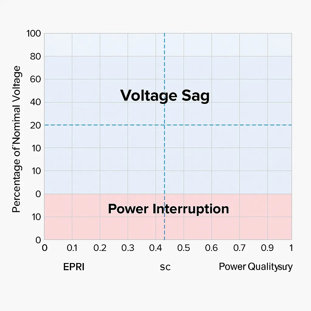
Figure 1: Comparison of voltage sags and interruptions. The blue shaded area represents voltage sags: 90% to 10% of nominal voltage; the red area represents interruptions: 10% of nominal or below. Image source: EPRI.
Difference Between Voltage Sags and Interruptions
A voltage sag occurs when the system voltage briefly falls below 90% of nominal (for example, 108 V on a 120 V system). A voltage interruption occurs when voltage falls to 10% of nominal or below (for example, 12 V on a 120 V system). Research by the Electric Power Research Institute (EPRI) shows that almost all voltage sags last less than 1 second—most under 0.5 second—and in most cases the magnitude of the drop exceeds 50% of nominal voltage.
Voltage sags have two principal descriptors: the remaining voltage as a percentage of nominal and the duration of the sag. Figure 2 shows 60 Hz three-phase voltage waveforms and the measured RMS voltage trace. In the upper plot, the blue trace labeled "Channel 1" represents phase A (the others are phases B and C) and shows waveform disturbance slightly longer than a single cycle (at 60 Hz there are 60 cycles per second). In the lower plot, the voltage dips to roughly 25% of nominal, about 68 V, for a very short interval. The entire event occurs within 0.04 second.
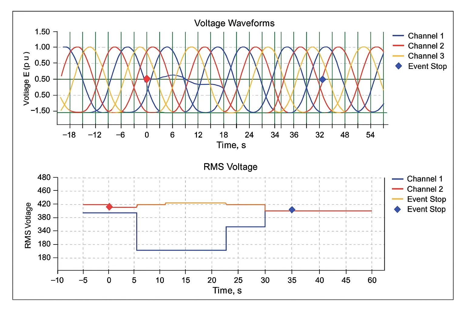
Figure 2: Voltage waveforms and RMS over time: a momentary short circuit in the distribution system can cause a voltage sag.
Common Causes
Storms and animals contacting grounded electrical equipment are common causes of both interruptions and voltage sags. Multiple distribution feeder circuits connected to a substation transformer secondary are analogous to a hand (the transformer secondary) with outstretched fingers (the distribution feeders). These feeders may extend many miles. If a tree limb contacts one feeder during a storm, that feeder may short to ground, phase-to-phase, or phase-to-ground (a fault). All other feeders connected to the same transformer secondary will experience a voltage sag and, depending on circumstances, may drop to 10% of nominal or below.
The breaker on the faulted feeder may trip to clear the fault, disconnecting downstream loads; this is an interruption on that feeder. Once the breaker opens, the voltage sag on the other feeders ends. Sags can therefore be very brief. Depending on breaker reclosing settings and the nature of the fault, the interruption on the faulted feeder may also be momentary.
Why Voltage Sags Are a Problem for Industrial Equipment
Inherent Sensitivity of Industrial Controls
In the United States most electrical equipment is designed to operate at steady-state voltages within ±10% of nominal, so the equipment design assumes a relatively constant supply. Historically, industrial controls have been designed for 120 V AC.
Figure 3 shows an example of interphase connections for a control power transformer (CPT). Inside the control circuit is an emergency off circuit (EMO) with an AC pilot relay that supplies 120 V to the main contactor coil, which in turn powers the process. AC controls typically do not store energy. At 60 Hz the AC voltage crosses zero 120 times per second. Therefore during a voltage sag there is nothing to prevent the control voltage from falling. When controls stop operating, the process stops.
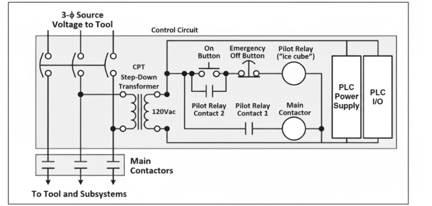
Figure 3: Typical AC control schematic: the control power transformer (CPT) supplies relays, contactors, PLC power and I/O. Other components may include DC supplies and adjustable speed drives (ASD).
Control components are sensitive to voltage sags, and a single component can stop the process. For example, an AC pilot relay typically drops out around 70% of nominal voltage, which has the same effect as pressing an emergency stop.
Other potentially sensitive components include programmable logic controller (PLC) power supplies (or other DC supplies), I/O modules, adjustable speed drives, and other contactors. When a system contains multiple process stages, different control circuits may be powered at different times. Depending on when a sag occurs, the process may stop at different stages.
Some components in process control are inherently sensitive to instant reductions in supply voltage, and these components are the reason industrial processes are highly sensitive to power quality events. These voltage transients are typically caused by distribution system events that create phase-to-phase or phase-to-ground faults. Understanding the root cause of process sensitivity to voltage sags is important when identifying potential solutions.
Improving Power Quality
Addressing power quality issues can increase equipment uptime and improve the reliability of production operations. Recommendations include:
- Understand your power quality environment and develop solutions appropriate to your situation.
- Do not assume a battery-based uninterruptible power supply is always required.
- Avoid using sensitive AC components in control circuits where possible.
- Embed robustness by using AC- or DC-based controls compliant with IEEE 1668 or SEMI F47.
- Configure voltage ride-through for motor drive systems.