 ALLPCB


Overview
Mastering UART and other communication interfaces is important for embedded beginners. It deepens understanding of communication protocols and methods, improves debugging skills and interface design ability, and broadens application scope while fostering system-level thinking. This article provides a detailed explanation of the UART interface for embedded learners.
1. Basic Concepts
UART stands for Universal Asynchronous Receiver/Transmitter. It refers both to a hardware device and to an asynchronous serial communication protocol. As an asynchronous, serial, full-duplex protocol, UART transmits data one bit at a time. In the protocol, a high voltage level on the signal line represents a logical "1" and a low level represents a logical "0". UART requires a simple wiring: a pair of transmission lines can provide bidirectional communication, which reduces cost at the expense of lower speed compared with parallel or synchronous methods.
Below are concise comparisons to clarify differences among full duplex vs half duplex, serial vs parallel, and asynchronous vs synchronous communication:
(1) Full duplex
Both parties can send and receive data simultaneously without interfering with each other. Typically two physical lines or channels are used: one for transmit and one for receive. A typical example is a telephone, where both participants can speak and listen at the same time.
(2) Half duplex
Parties alternate between sending and receiving but cannot do both at the same time. When one device transmits, the other must be in receive mode. Only one physical line or channel is required, used alternately for sending and receiving. A walkie-talkie is a typical half-duplex device.
(3) Serial
Serial transmission sends data bits sequentially, one after another, over a single communication line or channel. Each bit is sent or received in order, often synchronized to a clock signal. Serial links use fewer physical wires and suit long-distance or resource-constrained scenarios, though they are generally slower than parallel transmission.
(4) Parallel
Parallel transmission sends multiple bits simultaneously, each bit on its own line. This enables higher throughput but requires more wiring and more complex hardware, making it less suitable for long-distance links.
(5) Synchronous
Synchronous transmission uses a shared clock signal so sender and receiver are synchronized. This supports high data rates and accurate timing, and is common in applications requiring precise timing control, such as memory buses and Ethernet.
(6) Asynchronous
Asynchronous transmission does not use an external clock. Instead, start and stop bits are added to each data packet to identify packet boundaries. The sender and receiver use independent clocks. Asynchronous schemes are simpler and more flexible, suitable for lower-speed links where precise timing is not required.
2. Operating Mode
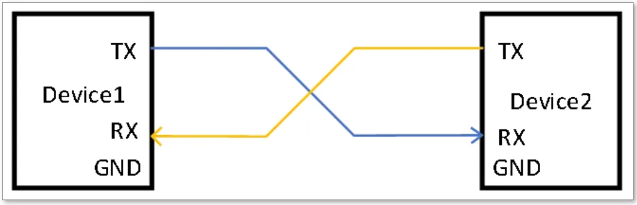
A UART channel uses two data lines. Each device has an RX pin (receive) and a TX pin (transmit). Each device's RX is connected to the other device's TX. No clock line is used in this connection.
After wiring, UART transmits byte-oriented data, sending bits in sequence. The receiving UART reassembles these bits into complete bytes.
UART transmits data in frames.
Start bit: A logical "0" sent first to indicate the start of a character.
Data bits: Typically 5 to 8 bits carrying logical "0" or "1". For example, ASCII uses 7 bits, extended formats use 8 bits. Bits are sent least significant bit first.
Parity bit: Optional bit that makes the total number of "1" bits even (even parity) or odd (odd parity).
Stop bit(s): Mark the end of the character. Stop bits are high level and can be 1, 1.5, or 2 bits long.
Idle state: The line stays at logical "1" when no data is being transmitted.
Baud rate is an important parameter for UART. It defines the symbol rate in bauds and determines bit transmission speed. Both communicating parties must use the same baud rate to ensure correct data transfer. Common baud rates include 9600 and 115200.
3. Common Voltage Standards
UART defines the logical frame format, but not the physical voltage levels. Voltage standards determine signal voltage ranges, transmission distance, and noise immunity. Different standards are used to meet different application requirements.
(1) TTL
TTL-based UART is the simplest physical implementation: digital IO outputs drive the physical signal levels directly. TTL logic levels are commonly 5V, 3.3V, or 1.8V.
Typical logic thresholds for different voltage levels are shown below:
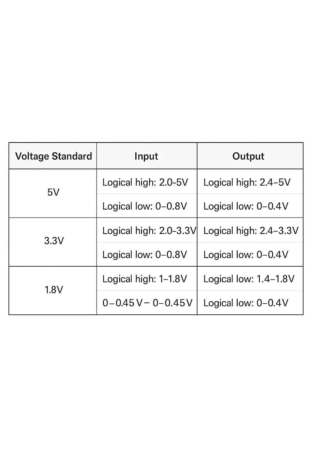
Physically, devices share a common ground and use a single signal line for one-way communication. Two lines enable full-duplex communication. TTL UART is suitable for short distances and is widely used in DIY electronics, embedded systems, sensors, and actuators.
(2) RS-232
RS-232 is an interface standard specified by the Electronic Industry Association for serial data communication, commonly used for computer serial ports and peripheral connections like modems and printers. It is intended for short-distance communication.
RS-232 voltage levels typically range from -15V to +15V, with ±12V common. The standard defines input and output voltage ranges for logical states. RS-232 lines idle at negative voltages; during data transmission voltages swing between positive and negative levels. The large voltage swing improves noise immunity and provides reliable short-distance links.
(3) RS-485
RS-485 is a multi-point, differential serial communication standard designed for longer distances and noisy environments. It supports multiple nodes on the same bus and typically works over distances up to 1200 meters. RS-485 uses differential signaling where the voltage difference between the pair represents logical states. It offers strong noise suppression, scalable cable length, and supports multiple devices on one bus using low-power drivers and receivers.
Conclusion
This article introduced the UART interface, covering basic concepts, operating modes, frame structure, baud rate considerations, and common physical voltage standards. The information is intended to help embedded learners understand UART fundamentals and practical implementation considerations.


