 ALLPCB


Introduction:
In embedded systems, the watchdog is an important mechanism to maintain system stability. Typical implementations rely on the application layer to feed the watchdog, which can be unstable and cannot handle exceptions during system boot. This article describes a technique on the T113-I platform for seamless watchdog handover from U-Boot to the kernel, implementing fully automatic watchdog feeding to improve system reliability.
1. Challenges
Implementing a fully automatic watchdog feeding mechanism from power-up ensures the system will not reset due to watchdog timeout at any stage. High-reliability embedded systems often require strict and timely supervision and therefore use watchdog chips with very short timeouts.
When the feeding interval is short, the seamless switch from U-Boot to the kernel becomes a major challenge in high-reliability embedded system design.
2. Environment
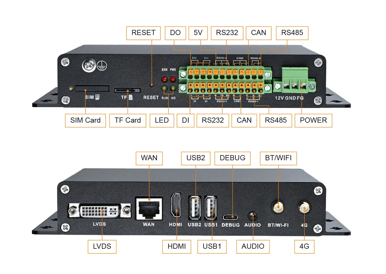
- Carrier board: AC 113I-92M-SNLI industrial core board, based on the Allwinner T113-I processor
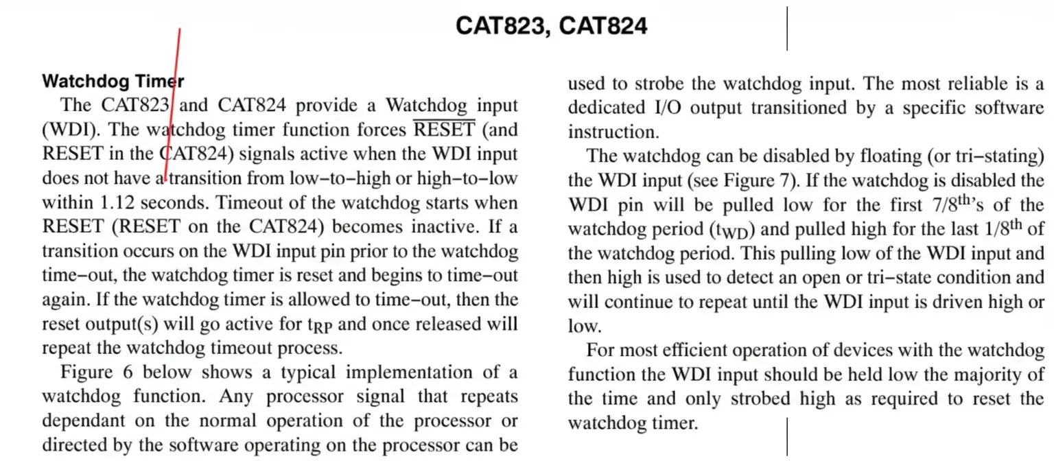
- Watchdog chip: 3PEAK TPV6823S-TR, reset timeout 1.12 seconds
- SDK version: talowe-T113-I-Tina-sdk.tar.gz
- Virtual machine: Ubuntu 20.04
3. Design
Given the 1.12 second reset limit, the following staged plan was defined to ensure timely feeding from U-Boot through kernel:
- Stage 1: U-Boot GPIO toggle to verify the ability to control the watchdog pin.
- Stage 2: U-Boot watchdog feeding to ensure the system does not timeout while at the U-Boot prompt.
- Stage 3: Kernel watchdog feeding to ensure continued feeding after the kernel boots.
- Stage 4: Seamless handover from U-Boot to kernel so the watchdog does not timeout from power-up through full system boot.
4. Implementation Steps
4.1 U-Boot GPIO toggle test
The watchdog pin is PE1. First verify control of this pin by consulting the T113-i_User_Manual_V1.5.pdf and locating PE register addresses.
Create gpio_toggle.c under brandy/brandy-2.0/u-boot-2018/cmd/ to set PE1 as output and toggle its level.
#include#include#define T113_I_GPIOE_CFG0 0x020000C0#define T113_I_GPIOE_CFG1 0x020000C4#define T113_I_GPIOE_DAT 0x020000D0#define T113_I_GPIOE_DRV0 0x020000D4#define T113_I_GPIOE_DRV1 0x020000D8#define T113_I_GPIOE_PULL0 0x020000E4int gpio_toggle(cmd_tbl_t* cmdtp, int flag, int argc, char* const argv[]) { printf("## [te] st gpio Toggle...\n"); // Set PE1 to output mode unsigned int* PE1_CFG0 = (unsigned int*)(T113_I_GPIOE_CFG0); unsigned int PE1_CFG0_val = readl(PE1_CFG0); PE1_CFG0_val &= ~(0xf << 4*1); PE1_CFG0_val |= (0x1 << 4*1); writel(PE1_CFG0_val, PE1_CFG0); // Toggle output level unsigned int* PE1_DAT = (unsigned int*)(T113_I_GPIOE_DAT); unsigned int PE1_DAT_val = readl(PE1_DAT); PE1_DAT_val ^= (0x1 << 1); writel(PE1_DAT_val, PE1_DAT); return 0;}U_BOOT_CMD(gpio_toggle, 1, 0, gpio_toggle, "talowe test gpio Toggle", "no parameters\n");Modify the Makefile and Kconfig to add the new command.
brandy/brandy-2.0/u-boot-2018/cmd/Makefileobj-$(CONFIG_CMD_GPIO_TOGGLE) += gpio_toggle.obrandy/brandy-2.0/u-boot-2018/cmd/Kconfigconfig CMD_GPIO_TOGGLE bool "GPIO toggle" help Activate this option to test GPIO toggle.Enable CONFIG_CMD_GPIO_TOGGLE in sun8iw20p1_auto_t113_i_defconfig and build U-Boot.
brandy/brandy-2.0/u-boot-2018/configs/sun8iw20p1_auto_t113_i_defconfigCONFIG_CMD_GPIO_TOGGLE=yOn power-up press and hold the 's' key to enter the U-Boot prompt, then run the gpio_toggle command. Use a multimeter to observe PE1 toggling once per command execution, confirming success.
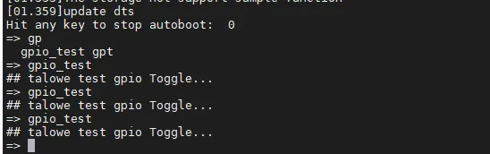
With register toggling verified, proceed to the next step.
4.2 U-Boot automatic feeding on PE1
Implement the built-in U-Boot hw_watchdog interface to initialize PE1 as an output and toggle it during watchdog reset.
#include#include#include#define T113_I_GPIOE_CFG0 0x020000C0#define T113_I_GPIOE_CFG1 0x020000C4#define T113_I_GPIOE_DAT 0x020000D0#define T113_I_GPIOE_DRV0 0x020000D4#define T113_I_GPIOE_DRV1 0x020000D8#define T113_I_GPIOE_PULL0 0x020000E4void hw_watchdog_reset(void) { if (get_boot_work_mode()) return; unsigned int* PE1_DAT = (unsigned int*)(T113_I_GPIOE_DAT); unsigned int PE1_DAT_val = readl(PE1_DAT); PE1_DAT_val ^= (0x1 << 1); writel(PE1_DAT_val, PE1_DAT);}void hw_watchdog_init(void) { // Set PE1 to output mode unsigned int* PE1_CFG0 = (unsigned int*)(T113_I_GPIOE_CFG0); unsigned int PE1_CFG0_val = readl(PE1_CFG0); PE1_CFG0_val &= ~(0xf << 4*1); PE1_CFG0_val |= (0x1 << 4*1); writel(PE1_CFG0_val, PE1_CFG0); // Set PE1 drive strength (default is 1, optional) // unsigned int *PE1_DRV0 = (unsigned int *)(T113_I_GPIOE_DRV0); // unsigned int PE1_DRV0_val = readl(PE1_DRV0); // PE1_DRV0_val &= ~(0x3 << 4*1); // PE1_DRV0_val |= (0x10 << 4*1); // writel(PE1_DRV0_val, PE1_DRV0); // Set PE1 level; since the circuit leaves this pin floating, toggle it once initially // unsigned int *PE1_DAT = (unsigned int *)(T113_I_GPIOE_DAT); // unsigned int PE1_DAT_val = readl(PE1_DAT); // PE1_DAT_val ^= (0x1 << 1); // writel(PE1_DAT_val, PE1_DAT); // Default is no pull-up/down, which matches requirements so no action needed hw_watchdog_reset();}Add the driver build options:
1 obj-$(CONFIG_T113_I_WATCHDOG_REG) += t113_I_watchdog_reg.oconfig T113_I_WATCHDOG_REG bool "T113_I hw watchdog" depends on ARCH_SUNXI select HW_WATCHDOG help Say Y here to enable the T113_I hw watchdog driver.Add the watchdog driver option to configuration files and modify the Allwinner board-level file board.c to call hw_watchdog_init() during board initialization, enabling watchdog feeding during the U-Boot stage.
diff --git a/brandy/brandy-2.0/u-boot-2018/board/sunxi/board.c b/brandy/brandy-2.0/u-boot-2018/board/sunxi/board.cindex 0019f45..4233b22 100644--- a/brandy/brandy-2.0/u-boot-2018/board/sunxi/board.c+++ b/brandy/brandy-2.0/u-boot-2018/board/sunxi/board.c@@ -54,6 +54,9 @@#endif#include#include+#ifdef CONFIG_T113_I_WATCHDOG_REG+#include+#endifint __attribute__((weak)) sunxi_set_sramc_mode(void)@@ -219,6 +222,9 @@int board_init(void) sunxi_plat_init();+#ifdef CONFIG_T113_I_WATCHDOG_REG+ hw_watchdog_init();+#endif int work_mode = get_boot_work_mode(); ret = axp_gpio_init();Verification: Enable the hardware DIP switch reserved for the watchdog circuit. On power-up, enter the U-Boot prompt; the system does not reset due to timeout, indicating the U-Boot feeding implementation works.
4.3 Kernel automatic feeding on PE1
Enable the kernel option:
CONFIG_GPIO_WATCHDOG=yAdd watchdog configuration to the device tree:
watchdog: watchdog { compatible = "linux,wdt-gpio"; gpios = <&pio PE 1 GPIO_ACTIVE_HIGH>; hw_algo = "toggle"; hw_margin_ms = <1000>; #always-running = "true";};Verification: After boot, enable the hardware DIP switch reserved for the watchdog circuit. The system does not reboot, indicating kernel feeding works correctly.
4.4 Handover from U-Boot to kernel
A key step: testing showed the watchdog may time out around 0.2 seconds into kernel startup. To avoid missed feeding due to excessive early-stage logging, reduce kernel log verbosity so the kernel can promptly take over feeding.
Change loglevel from 8 to 5 or 6 in device/config/chips/t113_i/configs/evb1_auto/buildroot/env.cfg.
diff --git a/device/config/chips/t113_i/configs/evb1_auto/buildroot/env.cfg b/device/config/chips/t113_i/configs/evb1_auto/buildroot/env.cfgindex bc1d41d..52d32d2100755--- a/device/config/chips/t113_i/configs/evb1_auto/buildroot/env.cfg+++ b/device/config/chips/t113_i/configs/evb1_auto/buildroot/env.cfg@@ -8,7 +8,7 @@ mmc_root=/dev/mmcblk0p5 mtd_name=sysroot fstype=ubifs,rw init=/init- loglevel=8+ loglevel=5 cma=16M mac=wifi_mac=5. Conclusion
Following these steps, a seamless watchdog handover from U-Boot to the kernel was implemented on the T113-I platform. The system automatically feeds the watchdog from power-up through runtime without application-layer intervention, improving stability and reliability. This approach is applicable to embedded projects requiring high stability, such as industrial control and IoT devices.


