ALLPCB


In the high-stakes world of military radar systems, every detail matters. One critical factor that can make or break performance is controlled impedance in PCB design. But why is controlled impedance so important for military radar PCBs? Simply put, it ensures signal integrity, minimizes data loss, and supports the high-frequency signals essential for radar accuracy and reliability. In this blog, we’ll dive deep into the role of controlled impedance, exploring key concepts like transmission line impedance, impedance matching, differential impedance, and TDR testing. Whether you’re an engineer or a designer, this guide will help you understand how to achieve optimal performance in military radar applications.
What is Controlled Impedance in PCB Design?
Controlled impedance refers to the precise management of electrical impedance in a printed circuit board (PCB) to ensure consistent signal transmission. In simpler terms, it’s about making sure that signals travel through the PCB without distortion or loss. Impedance, measured in ohms, is the resistance to the flow of alternating current (AC) signals, and in high-frequency applications like military radar, even small mismatches can lead to significant issues.
Military radar systems operate at extremely high frequencies, often in the gigahertz (GHz) range, where signals are highly sensitive to impedance variations. A typical target impedance for high-speed designs might be 50 ohms for single-ended signals or 100 ohms for differential pairs. If the impedance isn’t controlled, reflections, crosstalk, and signal degradation can occur, compromising the radar’s ability to detect and track targets accurately.
Why Controlled Impedance Matters in Military Radar Systems
Military radar systems are the backbone of defense operations, used for surveillance, target tracking, and missile guidance. These systems rely on high-speed, high-frequency signals to process data in real-time. Any signal distortion or loss can result in delayed responses or inaccurate readings, which could have catastrophic consequences in a combat scenario.
Controlled impedance in PCBs ensures that signals maintain their integrity as they travel through transmission lines. For example, a radar system transmitting at 10 GHz requires precise impedance matching to prevent signal reflections. Without this, up to 30% of the signal energy could be lost due to reflections, reducing the system’s effective range and accuracy.
Moreover, military environments are harsh, with extreme temperatures, vibrations, and electromagnetic interference (EMI). Controlled impedance helps mitigate EMI by ensuring signals are transmitted cleanly, reducing noise that could interfere with radar performance. This makes controlled impedance not just a technical requirement but a critical factor for mission success.
Key Concepts in Controlled Impedance for Military Radar PCBs
To fully grasp the importance of controlled impedance, let’s break down some essential concepts that play a role in military radar PCB design.
Transmission Line Impedance: The Foundation of Signal Integrity
Transmission line impedance is the characteristic impedance of the conductive paths (traces) on a PCB that carry high-frequency signals. In military radar designs, these traces act as transmission lines, and their impedance must match the source and load to prevent signal reflections. For instance, a common standard is to design traces with a 50-ohm impedance for single-ended signals to align with most high-frequency components.
If the transmission line impedance deviates even by 10%, reflections can occur, causing signal distortion. In radar systems, this could mean missing a fast-moving target or misinterpreting data. Designers achieve the desired impedance by carefully selecting trace width, thickness, and the dielectric material of the PCB, often using simulation tools to predict and adjust values.
Impedance Matching: Preventing Signal Loss
Impedance matching is the process of aligning the impedance of the PCB traces with the connected components, such as amplifiers or antennas in a radar system. When impedance is matched, the maximum amount of signal power is transferred, and reflections are minimized. For military radar operating at frequencies above 5 GHz, even a slight mismatch can lead to a 20% or higher signal loss, directly impacting detection range.
Designers often use techniques like adding termination resistors or adjusting trace geometry to achieve impedance matching. This is especially critical in radar systems where signal strength directly correlates with the ability to detect distant or low-visibility targets.
Differential Impedance: Supporting High-Speed Data
Differential impedance is crucial for differential signaling, a technique often used in high-speed digital circuits within radar systems. It refers to the impedance between two paired traces that carry complementary signals. In military radar, differential pairs are used to transmit data at rates exceeding 10 Gbps, requiring precise differential impedance, typically around 100 ohms.
Maintaining differential impedance ensures that noise and EMI are canceled out, as the two signals are equal in magnitude but opposite in phase. This is vital for radar systems operating in environments with high electromagnetic interference, as it preserves data integrity during critical operations.
TDR Testing: Verifying Controlled Impedance
Time Domain Reflectometry (TDR) testing is a method used to measure and verify controlled impedance in PCBs. During TDR testing, a fast electrical pulse is sent through the PCB trace, and any reflections caused by impedance discontinuities are analyzed. This helps identify issues like improper trace width or material defects that could affect signal integrity.
In military radar PCB manufacturing, TDR testing is often performed to ensure that impedance values are within a tight tolerance, typically ±10% of the target value (e.g., 50 ohms ±5 ohms). This rigorous testing is essential because even minor deviations can lead to performance issues in high-frequency radar applications. TDR testing provides a reliable way to validate designs before deployment in critical defense systems.
Challenges of Achieving Controlled Impedance in Military Radar PCBs
Designing PCBs for military radar with controlled impedance is not without challenges. The high-frequency nature of radar signals, combined with the demanding operational environment, creates unique obstacles for engineers.
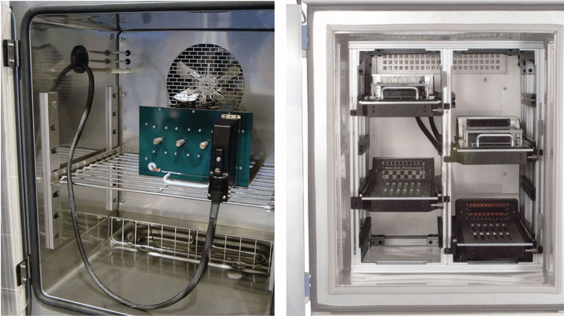
First, the materials used in PCBs must withstand extreme conditions while maintaining consistent dielectric properties. For instance, the dielectric constant (Dk) of the PCB material must remain stable across a temperature range of -40°C to 85°C to prevent impedance variations. High-performance materials like PTFE-based laminates are often used, but they can be costly and challenging to work with.
Second, the compact size of modern radar systems requires dense PCB layouts, increasing the risk of crosstalk and EMI. Designers must carefully route traces to maintain differential impedance and minimize interference, often relying on multilayer boards with dedicated ground planes.
Finally, manufacturing tolerances are incredibly tight in military applications. A trace width variation of just 0.1 mm can alter impedance by several ohms, leading to signal issues. This necessitates advanced fabrication techniques and thorough testing, like TDR, to ensure compliance with design specifications.
Best Practices for Controlled Impedance in Military Radar PCB Design
Achieving controlled impedance in military radar PCBs requires a combination of careful design, precise manufacturing, and rigorous testing. Here are some best practices to follow:
- Simulate Early and Often: Use simulation software to model transmission line impedance and differential impedance before fabrication. This helps identify potential issues early in the design phase.
- Choose the Right Materials: Select PCB materials with stable dielectric constants and low loss tangent for high-frequency signals. Materials with a Dk of 3.0 to 4.0 are often suitable for radar applications.
- Maintain Consistent Trace Geometry: Ensure uniform trace width and spacing, especially for differential pairs, to achieve the target impedance. For a 50-ohm single-ended trace, a width of 0.2 mm on a 1.6 mm thick board might be ideal, depending on the dielectric.
- Use Ground Planes: Incorporate solid ground planes beneath signal layers to stabilize impedance and reduce EMI, a critical factor in military environments.
- Validate with TDR Testing: Perform TDR testing during and after manufacturing to confirm that impedance values meet the design specifications, ensuring reliability in the field.
How Controlled Impedance Enhances Military Radar Performance
The benefits of controlled impedance in military radar PCBs directly translate to improved system performance. With proper impedance control, radar systems can achieve:
- Higher Accuracy: Clean signal transmission reduces errors in target detection and tracking, enabling precise identification of objects at ranges exceeding 100 kilometers.
- Greater Reliability: Consistent impedance minimizes signal loss and noise, ensuring radar systems function reliably even in harsh conditions.
- Faster Response Times: High-speed data transmission supported by differential impedance allows for real-time processing, critical for missile defense and threat detection.
In essence, controlled impedance is a foundational element that enables military radar systems to meet the stringent demands of modern defense applications.
Conclusion: Prioritizing Controlled Impedance for Mission-Critical Success
In military radar PCB design, controlled impedance is not just a technical detail—it’s a mission-critical requirement. By ensuring signal integrity through precise management of transmission line impedance, impedance matching, and differential impedance, designers can build radar systems that perform reliably under the most demanding conditions. Techniques like TDR testing further validate these designs, providing confidence in their real-world performance.
For engineers and designers working on military applications, mastering controlled impedance is essential to delivering systems that meet the highest standards of accuracy and reliability. By following best practices and leveraging advanced tools and materials, you can ensure that your PCB designs support the critical operations of military radar systems, safeguarding national security and mission success.
At ALLPCB, we’re committed to supporting your high-frequency PCB needs with precision manufacturing and expert guidance. Whether you’re tackling controlled impedance challenges or optimizing for military-grade performance, we’re here to help you achieve excellence in every design.