ALLPCB


Introduction
Automation is a major focus in industry, and servo motors play an important role, typically driving components that require precise speed or position control. Designers of automation equipment often face motor selection challenges because suppliers offer many models and parameters, which can confuse newcomers. This article shares practical experience from the author's work to assist readers.
1. Application scenarios
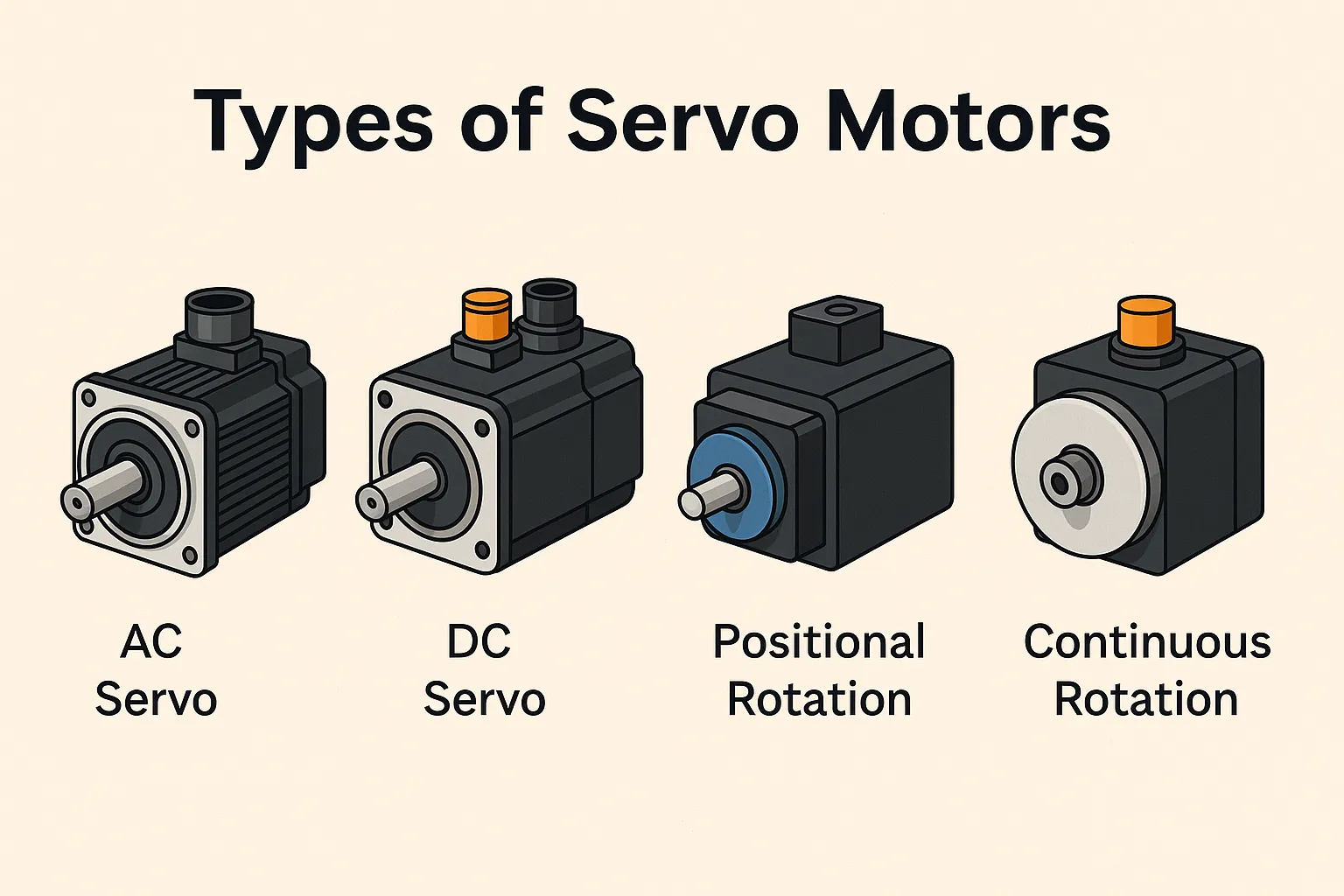
Control motors used in automation include servo motors, stepper motors, and variable-frequency (inverter) driven motors. Servo motors are chosen when a component requires relatively precise speed or position control.
The inverter plus variable-frequency motor control method changes the motor speed by altering the input frequency. It is generally used for speed regulation only.
Comparison between servo motors and stepper motors:
- a) Servo motors use closed-loop control, while stepper motors commonly operate open-loop.
- b) Servo motors use rotary encoders for measurement accuracy, while stepper motors use step angle. At typical product levels, servo accuracy can be orders of magnitude higher than stepper accuracy.
- c) Control interfaces can be similar (pulse or direction signals).
2. Power supply
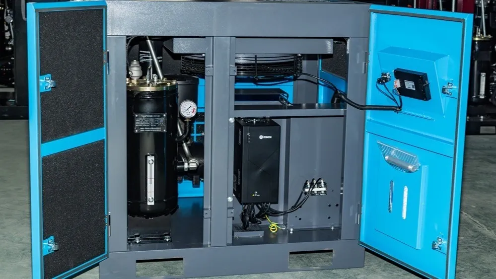
Servo motors are classified as AC servo motors or DC servo motors according to their supply. Selection is usually straightforward. Typical automation equipment provides standard 380 V industrial supply or 220 V supply, so choose a servo motor compatible with the available supply to avoid conversion. Mobile systems such as shuttle platforms in automated warehouses or AGVs often use onboard DC power and therefore typically use DC servo motors.
3. Holding brake
Consider the mechanism design and whether, when power is lost or when the system is stopped, the load will tend to rotate or fall. If there is a tendency to rotate, choose a servo motor with a holding brake.
4. Sizing calculation
Before sizing, determine the end-effector position and speed requirements, and then select the transmission mechanism. At that point you can choose the servo system and an appropriate gearbox.
Key parameters to consider during sizing include:
4.1 Power and speed
Calculate the required motor power and speed based on the mechanism type and the load's speed and acceleration requirements. Typically you also choose the gearbox ratio to match the selected motor speed.
In practice, for horizontal motion the friction coefficients and aerodynamic loads of transmission mechanisms are uncertain, so the formula P = T * N / 9549 may not precisely determine torque. Practically, the peak power needed from a servo motor often occurs during acceleration and deceleration. Using T = F * R = m * a * R allows a quantitative estimate of required motor torque and gearbox ratio, where m is load mass, a is load acceleration, and R is load rotation radius.
Additional considerations:
- a) Motor power margin.
- b) Transmission efficiency of the mechanism.
- c) Whether gearbox input and output torques meet requirements with an adequate safety factor.
- d) Potential future increases in required speed.
In some traditional industries, such as cranes where acceleration requirements are not strict, designers use empirical formulas for sizing.
Note: For vertically moving loads, include gravitational acceleration in calculations.
4.2 Inertia matching
For high-precision control of a load, consider whether the motor inertia matches the system inertia.
There is no single authoritative explanation online for why inertia matching is needed. The common practical rule is to reflect the system inertia to the motor shaft and keep the ratio of reflected inertia to motor inertia no greater than 10 (per manufacturers such as Siemens). A lower ratio yields better control stability but requires a larger motor and reduces cost effectiveness. For detailed calculation methods consult university-level theoretical mechanics resources.
4.3 Accuracy requirements
After accounting for gearboxes and transmission mechanisms, verify that the motor control accuracy meets load requirements. Consider gearbox backlash and any play in transmission elements.
4.4 Control matching
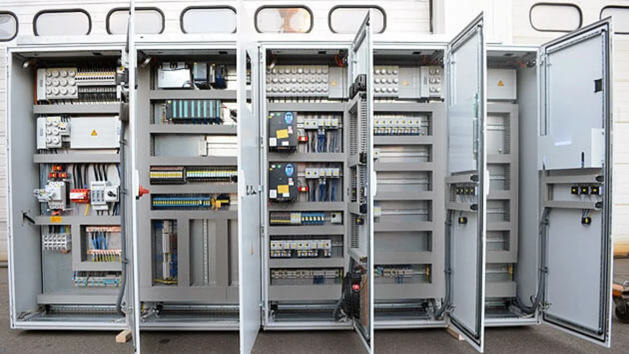
Coordinate with electrical design engineers on control interface compatibility, for example whether the servo controller communication method matches the PLC, the encoder type, and whether encoder data needs to be exposed.
5. Brands
There are many servo motor brands with varying performance. From general experience: if budget allows, consider European or American brands; then Japanese brands; followed by manufacturers from Taiwan and mainland China. Based on past projects, servo motor mechanics from mainland China are generally acceptable, while differences may exist in servo controller control algorithms, integration level, and stability.
- Europe/Americas: Siemens, ABB, Lenze.
- Japan: Panasonic, Mitsubishi, Yaskawa.
In automation design, leverage vendor technical support when available. Many servo manufacturers provide software tools: if you supply load, speed, and acceleration requirements, they can calculate and recommend suitable servo motors, which simplifies selection.