ALLPCB


1. Motor power and line current calculation
First calculate the line current for a 100 kW load. For a balanced three-phase circuit, the power formula is P = 1.732 I U cosφ. From this, the line current is:
I = P / (1.732 U cosφ)
Where P is the circuit power, U is the line voltage (380 V for three-phase), and cosφ is the power factor of an inductive load. Using cosφ = 0.8 as a representative value, the line current for a 100 kW load is:
I = 100000 / (1.732 × 380 × 0.8) = 100000 / 526.53 ≈ 190 A
Adjust the current value based on load characteristics and quantity. Motor starting currents are large (typically 4–7 times the running current), so consider starting current when selecting conductors and protection. Because starting time is short, a factor of 1.3–1.7 is commonly used for conductor selection; with 1.5 the design current would be 285 A. If many motors share the load and are not used simultaneously, apply a utilization factor (for example 0.5–0.8); using 0.8 here yields 228 A. Use this adjusted current to select cables, circuit breakers, contactors, and thermal overload relays.
Related Reading: Motor Delta and Star Connection Diagrams
Conductor selection
Based on typical allowable current tables, a 50 mm2 copper rubber-insulated cable or a 70 mm2 copper PVC-insulated cable is appropriate for the example current range.
Transformer selection
Transformer apparent power can be estimated as S = P / cosφ. For the 100 kW example:
S = 100 / 0.8 = 125 kVA
Select a transformer rated above 125 kVA. The allowable current of a 50 mm2 copper cable depends on installation method, ambient temperature, and cable construction. Representative long-term allowable currents for 50 mm2 XLPE cable are:
- Air-laid, 10 kV three-core: 231 A; 35 kV single-core: 260 A
- Direct-buried (soil thermal resistivity 100 °C·cm/W), 10 kV three-core: 217 A; 35 kV single-core: 213 A
2. Simplified cable sizing based on power (example)
Given: motor rated power 22 kW, rated voltage 380 V, transformer located 400 m from the site. Copper resistivity ρ = 0.0175 Ω·mm2/m.
1) Calculate apparent power at rated load:
S = P / cosφ = 22 / 0.8 = 27.5 kVA
2) Calculate rated current:
I = S / U = 27500 / 380 ≈ 73 A
There are empirical estimation rules for conductor allowable current, typically for aluminum-core insulated conductors under standard conditions. These rules give approximate multipliers of conductor cross-section to estimate allowable current. For small cross-sections (≤ 2.5 mm2), the multiplier is about 9. For larger sections the multiplier decreases progressively: 4 mm2 × 8, 6 mm2 × 7, 10 mm2 × 6, 16 mm2 × 5, 25 mm2 × 4. For sections from 50 mm2 upward, multipliers are grouped in pairs and decrease by 0.5 each group, e.g., 35 mm2 × 3.5 = 122.5 A; 50 and 70 mm2 use a multiplier of 3; 95 and 120 mm2 use 2.5, and so on.
These multipliers apply to aluminum-core conductors at an ambient temperature of 25 °C. For long-term ambient temperatures above 25 °C, reduce allowable current by 10%. For copper conductors, allowable current is higher than aluminum of the same cross-section; a practical approach is to use the multiplier for the next larger aluminum conductor when estimating a copper conductor.
3) Voltage drop method to size conductor cross-section:
Assume motor minimum operating voltage 360 V and transformer secondary 380 V, so allowable voltage drop ΔU = 20 V. At rated current:
R_line = ΔU / I = 20 / 73 ≈ 0.27 Ω
From R_line = ρ L / S, conductor cross-section S = ρ L / R_line = 0.0175 × 400 / 0.27 ≈ 24.62 mm2
Conclusion: select a 25 mm2 copper cable.
3. Selecting circuit breakers, overload relays, and contactors
Example: for an 18.5 kW motor with rated current about 37 A. A common rule of thumb is that 1 mm2 of copper conductors can carry 4–6 A; using 5 A/mm2 as a midpoint yields required cross-section 37 / 5 = 7.4 mm2. Standard cables are 6 mm2 and 10 mm2; for reliability, choose 10 mm2 if the motor operates near rated load. If the motor normally runs well below rated load, 6 mm2 may be acceptable.
Approximate power-to-current ratios for common voltages and three-phase motors:
- 220 V three-phase: 1 kW ≈ 3.5 A
- 380 V three-phase: 1 kW ≈ 2.0 A
- 660 V three-phase: 1 kW ≈ 1.2 A
- 3 kV: approximately 4 kW per 1 A
- 6 kV: approximately 8 kW per 1 A
Example: a three-phase asynchronous motor 7.5 kW, 4-pole typically has a rated current around 15 A, but consult the nameplate for exact values.
Selection guidelines
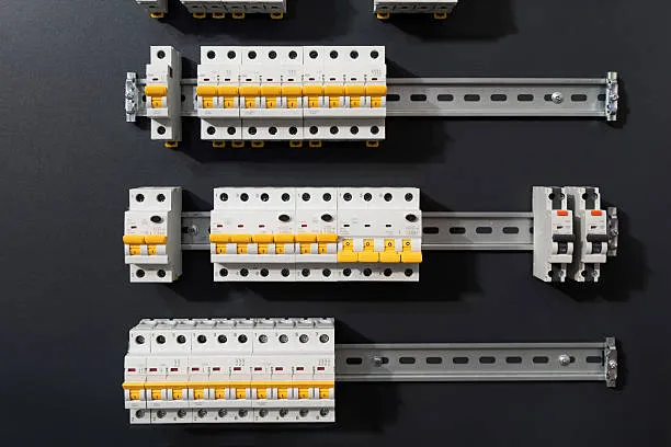
- Circuit breaker: select a breaker rated at about 1.5–2.5 times the motor rated current so the breaker can tolerate frequent starts while providing short-circuit protection. Common miniature circuit breaker types include DZ47 series types for low-voltage applications.
- Conductor: choose a conductor with adequate allowable current. If the motor starts frequently, choose a larger cross-section to reduce heating during starts.
- AC contactor: select a contactor sized for about 1.5–2.5 times the motor rated current. Verify auxiliary contact requirements to ensure sufficient auxiliary contacts are available for control circuits.
- Thermal overload relay: set the relay to 1–1.2 times the motor rated current, typically around 1.1 × rated current for protection while allowing start-up inrush.
Additional practical rules for multiple motors and long runs:
- For multiple motors, sum their rated powers. Some practical estimations multiply this sum by a factor to approximate combined current; calculate precisely when possible.
- For short runs (within 50 m), a quick sizing rule is conductor cross-section ≈ total current / 4 (with margin).
- For longer runs (over 50 m), a quick rule is conductor cross-section ≈ total current / 3 (with margin).
- For very large cables (above about 120 mm2) use lower current density values and consult detailed cable tables and standards.
Related Reading: Motor Selection for Robotics: Matching Torque, Speed, and Precision Requirements
4. Summary
Circuit breaker selection: choose a breaker rated around 2.5 times the motor rated current, with the breaker trip setting (or downstream protective setting) around 1.5 times the motor rated current. This balances tolerance for frequent starts and short-circuit sensitivity.
Thermal overload relay: set at approximately 1.1 times the motor rated current.
AC contactor: select a contactor rated for about 2.5 times the motor rated current to ensure reliable operation under frequent starting conditions.