ALLPCB


When it comes to designing and manufacturing printed circuit boards (PCBs), one of the most critical aspects to consider is the drilled hole diameter. Whether you're creating vias for electrical connections or holes for mounting components, understanding the minimum drill size and drill requirements is essential for a successful PCB design. In this comprehensive guide, we'll dive deep into the specifics of drilled hole diameters, the minimum sizes you can achieve, and the key requirements to ensure your PCB is manufactured without issues.
At the outset, let's address the core concern: the minimum drill size for PCB holes typically starts at around 0.15 mm for standard drilling processes, while advanced techniques like laser drilling can achieve even smaller holes down to 0.1 mm. These limits depend on the manufacturing capabilities and the type of hole, such as plated through holes (PTH) or non-plated through holes (NPTH). Now, let's explore this topic in detail to help you design with precision and avoid common pitfalls.
Why Drilled Hole Diameter Matters in PCB Design
The drilled hole diameter plays a pivotal role in the functionality and reliability of a PCB. Holes are used for various purposes, including mounting components, creating vias for interlayer connections, and securing the board to a chassis. If the hole size is too small, components may not fit, or electrical connections could fail. If it's too large, it can weaken the board structure or cause issues with soldering and plating.
Understanding the minimum drill size and requirements ensures that your design aligns with manufacturing capabilities, reducing the risk of delays or defects. This is especially important for high-density designs where space is limited, and smaller vias are necessary to route signals efficiently.

What Is the Minimum Drill Size for PCB Holes?
The minimum drill size refers to the smallest diameter of a hole that can be reliably drilled into a PCB during manufacturing. This size is influenced by several factors, including the type of drilling technology used, the material of the PCB, and the specific requirements of the design.
For standard mechanical drilling, the minimum drill size is often around 0.15 mm (6 mils). This size is suitable for most vias and small through-hole components. However, for more advanced applications requiring micro-vias, laser drilling technology can achieve holes as small as 0.1 mm (4 mils) or even smaller in specialized cases. It's worth noting that not all manufacturers support such small sizes, so it's crucial to confirm capabilities before finalizing your design.
The choice of drill size also depends on whether the hole is a plated through hole (PTH) or a non-plated through hole (NPTH). PTHs, which are used for electrical connections, require additional plating processes, which can slightly reduce the final hole diameter. NPTHs, often used for mounting or alignment, do not require plating and can sometimes be drilled to slightly smaller sizes without additional constraints.
Key Data Point: Standard minimum drill size for PTH vias is typically 0.15 mm, while NPTH can sometimes be as low as 0.1 mm with laser drilling, depending on the manufacturer’s equipment.
Related Reading: Minimum Drill Size for Non Plated Through Holes (NPTH): Applications and Guidelines
Factors Affecting Minimum Drill Size
Several factors determine the smallest possible drilled hole diameter in a PCB. Understanding these can help you make informed decisions during the design phase.
1. Manufacturing Technology
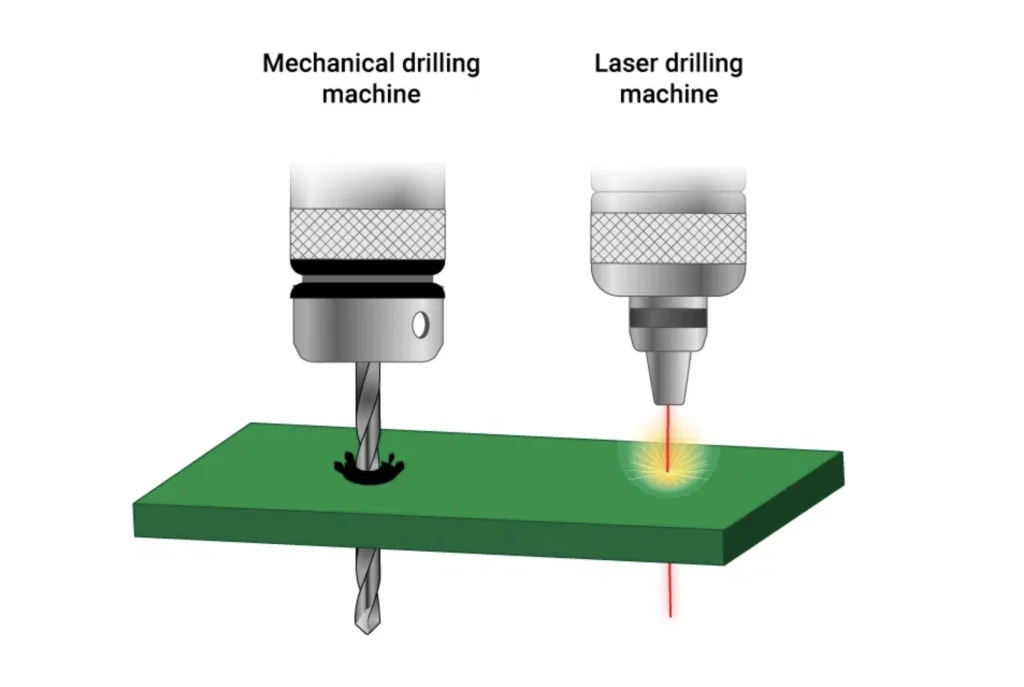
The type of drilling technology used has a significant impact on the minimum achievable hole size. Mechanical drilling, the most common method, uses physical drill bits and is limited by the smallest available bit size and the risk of bit breakage at very small diameters. Laser drilling, on the other hand, uses focused beams to create holes and can achieve much smaller sizes with higher precision, often down to 0.1 mm or less.
Related Reading: The Ultimate Guide to Minimum Drill Size for Through Hole Components: Choosing the Right Bit
2. PCB Material
The material of the PCB also affects drilling capabilities. Standard FR-4 material, a common choice for PCBs, can handle smaller drill sizes relatively well. However, harder or more specialized materials, such as high-frequency laminates or metal-core boards, may pose challenges, requiring larger minimum drill sizes or specialized equipment.
3. Aspect Ratio
The aspect ratio, which is the ratio of the hole depth to its diameter, is another critical factor. A high aspect ratio (e.g., a deep hole with a small diameter) can lead to drilling issues like bit deflection or breakage. For standard PCBs, an aspect ratio of 10:1 or lower is often recommended to ensure reliable drilling. For example, a 1.6 mm thick board should ideally have a minimum drill size of 0.16 mm to maintain this ratio.
4. Plating Requirements
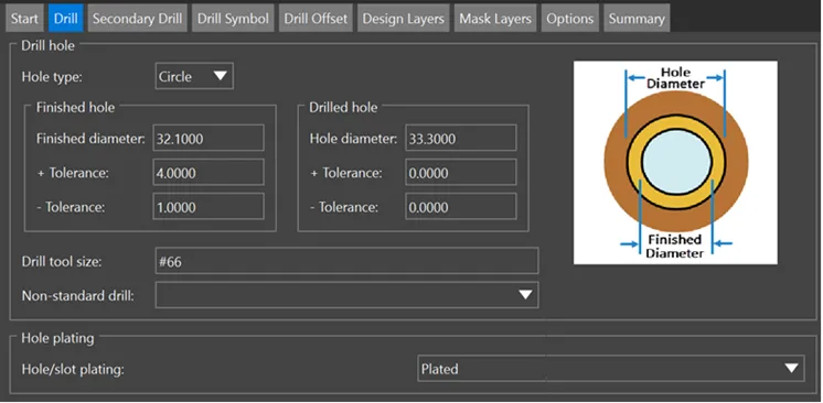
For PTHs, the plating process adds a layer of copper inside the hole, reducing the final inner diameter. Designers must account for this by specifying a slightly larger drilled hole diameter (often 0.1 mm larger than the desired finished size) to ensure the hole remains functional after plating.
Drill Requirements for PCB Manufacturing
Beyond the minimum drill size, there are several other drill requirements to consider to ensure your PCB design is manufacturable and meets performance standards. These requirements often depend on the complexity of your design and the specific application of the board.
1. Hole Tolerance
Hole tolerance refers to the acceptable deviation in the drilled hole diameter from the specified size. Standard tolerances are typically ±0.05 mm for smaller holes and ±0.1 mm for larger ones. Tight tolerances are crucial for high-precision applications, such as boards with press-fit connectors or fine-pitch components, but they may increase manufacturing costs.
2. Annular Ring Size
The annular ring is the copper pad surrounding a drilled hole. For PTHs, the annular ring must be large enough to ensure a reliable electrical connection after drilling and plating. A common guideline is that the annular ring diameter should be at least 0.2 mm larger than the drilled hole diameter on each side. For a 0.3 mm hole, this means a minimum pad diameter of 0.7 mm.
3. Drill-to-Copper Clearance
To prevent accidental short circuits or damage during drilling, there must be sufficient clearance between the edge of the drilled hole and nearby copper traces or planes. A typical clearance value is 0.2 mm or more, depending on the design rules and manufacturing capabilities.
4. Via Types and Sizes
Vias, which connect different layers of a PCB, often require specific drill sizes based on their type. Through-hole vias typically use a minimum drill size of 0.15 mm to 0.3 mm, while blind or buried vias may require smaller sizes achieved through laser drilling. The choice of via size also impacts signal integrity, especially in high-speed designs where smaller vias can reduce parasitic capacitance.
Key Data Point: For high-speed designs, using vias with a drilled hole diameter of 0.2 mm or smaller can help minimize signal loss, as larger holes introduce more capacitance, potentially affecting signal speeds above 1 GHz.
Best Practices for Specifying Drilled Hole Diameters
To avoid manufacturing issues and ensure your PCB performs as intended, follow these best practices when specifying drilled hole diameters in your design.
1. Consult Manufacturing Capabilities Early
Before finalizing your design, review the drilling capabilities of your chosen manufacturer. Confirm their minimum drill size, supported aspect ratios, and tolerances to ensure your design aligns with their processes. This step can save time and prevent costly redesigns.
2. Use Standard Drill Sizes
Whenever possible, stick to standard drill sizes (e.g., 0.2 mm, 0.3 mm, 0.6 mm) rather than custom sizes. Standard sizes are more likely to be readily available, reducing manufacturing time and cost. Most manufacturers provide a list of standard drill sizes they support.
3. Account for Plating in PTH Designs
For plated through holes, always specify the drilled hole diameter slightly larger than the desired finished hole size to account for the plating thickness. A common rule of thumb is to add 0.1 mm to the final size. For example, if you need a finished hole of 0.3 mm, specify a drilled diameter of 0.4 mm.
4. Optimize for High-Density Designs
In high-density interconnect (HDI) designs, space is often limited, requiring smaller vias and tighter spacing. Use laser-drilled micro-vias when possible, and work closely with your manufacturer to balance design requirements with manufacturing constraints.
Common Challenges with Small Drilled Hole Diameters
While smaller drilled hole diameters are often necessary for modern PCB designs, they come with certain challenges that designers must address.
1. Drill Bit Breakage
Smaller drill bits are more prone to breakage, especially in thicker boards or harder materials. This can lead to manufacturing delays or defects like misaligned holes. To mitigate this, keep aspect ratios low and avoid pushing the limits of minimum drill sizes unless absolutely necessary.
2. Plating Issues
For very small PTHs, achieving uniform copper plating inside the hole can be difficult. Poor plating can result in weak electrical connections or reliability issues over time. Ensure your design accounts for plating thickness and consult with your manufacturer if you're using holes near the minimum size limit.
3. Cost Implications
Smaller holes, especially those requiring laser drilling, often increase manufacturing costs due to the specialized equipment and slower processing times. Balance the need for small holes with budget constraints to optimize your design.
How to Choose the Right Drilled Hole Diameter for Your Project
Selecting the appropriate drilled hole diameter depends on the specific needs of your project. Here are some tips to guide your decision:
- For Through-Hole Components: Match the hole size to the component lead diameter, adding a small margin (typically 0.1 mm to 0.2 mm) for ease of insertion and soldering.
- For Vias: Use smaller diameters (0.15 mm to 0.3 mm) for signal vias in high-density designs, but ensure the size supports reliable plating and connection.
- For Mounting Holes: Choose larger diameters (often 1 mm or more) for NPTH mounting holes to accommodate screws or fasteners without stressing the board.
Always consider the trade-offs between hole size, board space, and manufacturing cost. A well-thought-out design prioritizes functionality while staying within practical limits.
Conclusion: Mastering Drilled Hole Diameters in PCB Design
Understanding the minimum drill size and drill requirements is a fundamental part of PCB design and manufacturing. By focusing on the drilled hole diameter, you can ensure that your board is both functional and manufacturable. Remember that standard minimum drill sizes start at around 0.15 mm for mechanical drilling and can go as low as 0.1 mm with laser drilling for advanced applications. Factor in tolerances, plating requirements, and aspect ratios to avoid common issues and optimize your design for success.
Whether you're working on a simple prototype or a complex high-density board, paying attention to these details will save you time, reduce costs, and improve the reliability of your final product. With the right approach, you can confidently design PCBs that meet both your technical needs and manufacturing constraints.