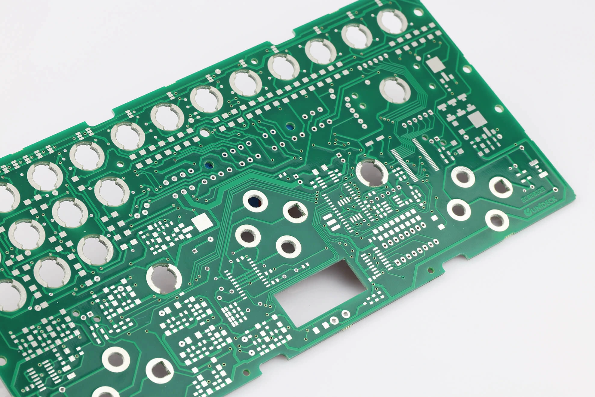
In the world of electronics, designing printed circuit boards (PCBs) for high-frequency applications requires precision and care, especially when adhering to lead-free standards. If you're searching for guidance on lead-free PCB impedance control, lead-free PCB signal integrity, or the right lead-free PCB material for RF, you've come to the right place. This blog post will walk you through the best practices for high-frequency PCB design and lead-free PCB high-speed design, ensuring your projects meet both performance and environmental requirements.
Whether you're an engineer working on RF circuits, telecommunications, or other high-speed systems, we'll cover the essentials of material selection, impedance management, signal integrity, and more. Let's dive into the details to help you achieve reliable and efficient designs.
Why Lead-Free PCB Design Matters in High-Frequency Applications
Lead-free PCB design has become a global standard due to environmental regulations like the Restriction of Hazardous Substances (RoHS) directive. These rules limit the use of harmful materials, including lead, in electronics. While transitioning to lead-free materials is crucial for compliance, it introduces challenges in high-frequency PCB design. Lead-free solders and materials often have different thermal and electrical properties compared to traditional lead-based options, which can impact signal performance and reliability in high-speed systems.
In high-frequency applications—such as RF circuits operating above 1 GHz or high-speed digital designs with data rates exceeding 10 Gbps—these challenges are even more pronounced. Small variations in material properties or design can lead to signal loss, crosstalk, or electromagnetic interference (EMI). That's why understanding best practices for lead-free PCB high-speed design is vital for engineers aiming to maintain performance while meeting regulatory standards.
Choosing the Right Lead-Free PCB Material for RF and High-Frequency Designs
Material selection is the foundation of any successful high-frequency PCB design. For lead-free designs, the choice of substrate and dielectric materials directly affects signal integrity and impedance control. Here are key considerations when selecting a lead-free PCB material for RF applications:
- Low Dielectric Constant (Dk): Materials with a low Dk (typically between 2.2 and 3.5) minimize signal delay and loss, which is critical for frequencies above 5 GHz. Popular choices include PTFE-based laminates and certain ceramic-filled materials.
- Low Dissipation Factor (Df): A low Df (ideally below 0.002) reduces signal attenuation, ensuring better performance in RF circuits. This is especially important for applications like wireless communication or radar systems.
- Thermal Stability: Lead-free soldering processes often require higher temperatures (up to 260°C), so the material must withstand these conditions without degrading. Look for materials with a high glass transition temperature (Tg) above 170°C.
- Compatibility with Lead-Free Finishes: Surface finishes like ENIG (Electroless Nickel Immersion Gold) or OSP (Organic Solderability Preservative) are commonly used in lead-free designs. Ensure the material supports these finishes without compromising reliability.
For example, in a 10 GHz RF design, using a material with a Dk of 2.2 can reduce signal propagation delay by approximately 15% compared to a material with a Dk of 4.0. This seemingly small difference can significantly impact performance in high-speed systems.
Lead-Free PCB Impedance Control: Key Techniques for High-Frequency Success
Impedance control is a cornerstone of lead-free PCB impedance control in high-frequency applications. Mismatched impedance can cause signal reflections, leading to data errors or signal loss. Here are best practices to achieve precise impedance control in lead-free designs:
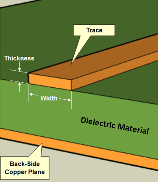
- Calculate Trace Width and Spacing: Use impedance calculators or simulation tools to determine the correct trace width and spacing for your target impedance (often 50 ohms for RF designs). For instance, at 5 GHz, a trace width of 10 mils on a 1.6mm thick substrate might achieve a 50-ohm impedance with a specific dielectric material.
- Maintain Uniform Stackup: Ensure consistent layer thickness and dielectric properties across the PCB stackup. Variations as small as 0.1mm in layer thickness can alter impedance by 5% or more, disrupting signal integrity.
- Minimize Vias: Vias introduce inductance and can disrupt impedance in high-frequency designs. If unavoidable, use back-drilling to reduce stub length and keep via transitions smooth.
- Account for Lead-Free Material Properties: Lead-free substrates may have slightly different dielectric constants compared to traditional materials. Always verify the material datasheet and adjust trace dimensions accordingly during design.
By focusing on these techniques, you can maintain tight impedance tolerances (typically within ±10%) required for high-speed and RF systems. Simulation tools can further help predict and refine impedance before manufacturing, saving time and cost.
Ensuring Lead-Free PCB Signal Integrity in High-Speed Designs
Signal integrity is a critical concern in lead-free PCB signal integrity for high-frequency applications. Poor signal integrity can result in data corruption, timing errors, or increased EMI. Follow these best practices to ensure clean signal transmission in lead-free PCB high-speed design:
- Ground Plane Design: Use continuous ground planes beneath signal traces to provide a low-impedance return path. Avoid splitting ground planes, as this can create noise in RF designs operating at 2.4 GHz or higher.
- Differential Pair Routing: For high-speed digital signals (e.g., data rates above 5 Gbps), route differential pairs with equal length and tight coupling to minimize skew. A length mismatch of just 5 mils can introduce a timing error of 30 ps at these speeds.
- Avoid Sharp Corners: Route traces with smooth curves or 45-degree angles instead of 90-degree bends to prevent signal reflections. This is especially important for frequencies above 1 GHz.
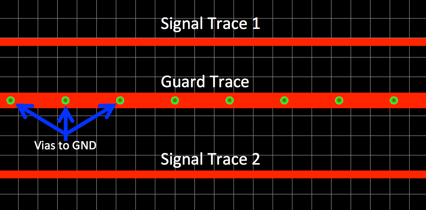
- Shielding for EMI: Use shielding techniques like guard traces or copper pours to isolate high-frequency signals from external interference. This is crucial in lead-free designs where material properties might amplify EMI risks.
Implementing these strategies ensures that your signals remain clear and reliable, even in complex high-frequency environments. Always test signal integrity using tools like time-domain reflectometry (TDR) during the design phase to catch issues early.
Thermal Management in Lead-Free High-Frequency PCB Design
Lead-free soldering processes require higher reflow temperatures, often reaching 240–260°C, compared to 220–240°C for traditional lead-based solders. This increase poses challenges for thermal management in high-frequency PCB design. Overheating can degrade materials, warp boards, or damage components, especially in RF circuits where thermal stability is critical.
To manage heat effectively, consider these tips:
- Use Thermal Vias: Place thermal vias under heat-generating components to transfer heat to inner layers or a heatsink. For example, a grid of 0.3mm vias spaced 1.2mm apart can reduce hotspot temperatures by up to 20°C.
- Select High-Tg Materials: As mentioned earlier, materials with a Tg above 170°C are better suited to withstand lead-free soldering temperatures without deforming.
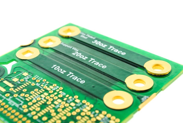
- Optimize Copper Thickness: Use thicker copper layers (e.g., 2 oz instead of 1 oz) in power and ground planes to improve heat dissipation, especially in designs with high current demands.
Proper thermal management not only ensures reliability but also maintains signal performance by preventing temperature-induced changes in material properties.
Layout Tips for Lead-Free PCB High-Speed Design
The layout phase is where many high-frequency design challenges are addressed. A well-planned layout minimizes noise, crosstalk, and signal loss. Here are essential layout tips for lead-free PCB high-speed design:
- Shorten Trace Lengths: Keep high-frequency signal traces as short as possible to reduce attenuation. For a 10 GHz signal, every inch of trace can introduce up to 0.5 dB of loss, depending on the material.
- Separate Analog and Digital Sections: Isolate analog RF signals from digital high-speed signals to prevent interference. Use separate ground planes if necessary, connected at a single point to avoid loops.
- Place Decoupling Capacitors Close to ICs: Position capacitors within 100 mils of power pins to filter noise effectively, ensuring stable operation at high frequencies.
- Follow 3W Rule for Spacing: Maintain a spacing of at least three times the trace width between adjacent high-speed traces to minimize crosstalk. For a 5-mil trace, this means a 15-mil separation.
These layout practices, combined with careful material selection and impedance control, form the backbone of a successful high-frequency design.
Testing and Validation for Lead-Free High-Frequency PCBs
After designing your PCB, thorough testing is essential to validate performance. For lead-free high-frequency designs, focus on these areas:
- Impedance Testing: Use a TDR to measure trace impedance and ensure it matches the design target (e.g., 50 ohms ±10%).
- Signal Integrity Analysis: Perform eye diagram tests for high-speed digital signals to check for jitter and timing issues. An eye opening of at least 60% is typically acceptable for data rates up to 10 Gbps.
- Thermal Testing: Use infrared cameras to identify hotspots during operation, ensuring temperatures stay within safe limits for lead-free materials.
- EMI Compliance: Test for radiated and conducted emissions to ensure the design meets regulatory standards, especially important in RF applications.
Testing early and often during the prototyping phase helps catch issues before mass production, saving time and resources.
Conclusion: Mastering Lead-Free PCB Design for High-Frequency Applications
Designing high-frequency PCBs with lead-free materials is a complex but achievable task when you follow the right practices. From selecting the best lead-free PCB material for RF to mastering lead-free PCB impedance control and ensuring lead-free PCB signal integrity, every step plays a crucial role in the success of your project. By focusing on material properties, thermal management, layout techniques, and thorough testing, you can create reliable and efficient designs for lead-free PCB high-speed design.
At ALLPCB, we're committed to supporting engineers with the tools and knowledge needed to excel in high-frequency applications. Use these best practices as a guide to elevate your designs, meet environmental standards, and achieve top-notch performance in your next project.
 ALLPCB


