ALLPCB


Overview
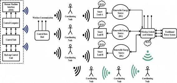
Devices required for smart grids, such as utility meters, renewable-energy sources, and equipment-monitoring systems, need accurate sensing of energy consumption. Several techniques have been developed to measure electrical power effectively, each with its own advantages and limitations. This article compares current transformers, Rogowski coils, Hall-effect sensors, and resistive shunts as options for energy measurement.
Energy consumption by electrical equipment is driving large-scale metering initiatives in many markets. Every smart meter requires an accurate method to determine current draw. This requirement also extends to an increasing number of systems that will connect to smart grids, such as renewable-energy systems, white goods, and data-center servers, so users and operators can track energy usage.
Deployment Considerations
Which sensing technology to use depends on the installation. The site may be single-phase, split-phase, or a three-phase distribution system. Typical residential installations in the United States use split-phase supply, providing 120 VAC or 240 VAC, which often favors current transformers for sensing. Commercial and large residential properties in Europe typically use three-phase supply. Single-family homes are generally single-phase, where simple shunt resistors can be used for metering. Three-phase systems often use current transformers or Rogowski coils, with Rogowski coils traditionally favored for large installations.
Resistive Shunts
Resistive shunts are the simplest and least expensive option because they are just low-value resistors placed in the electrical connection between the utility and the premises. The voltage drop across the shunt is proportional to current and frequency. However, this simple arrangement has drawbacks. The shunt itself must be physically large to handle the high currents typical of mains power. Self-heating and the power dissipated in the resistor cause issues, which is why shunts tend to be used in smaller household applications.
To limit power loss, shunts are typically in the hundreds of microohms. Signal conditioning circuits that detect the voltage drop must handle relatively small voltages, often less than 10 microvolts, requiring sensitive amplifiers to boost the signal. Parasitic inductance can introduce significant phase shift at low power factor, producing measurement errors. Regulatory requirements that enforce higher power factor have partly mitigated this problem.
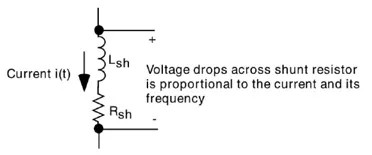
Figure 1: Principle of a current shunt.
Some resistors are designed specifically for current sensing using a Kelvin configuration, such as Ohmite's high-power TGHG series and low-power LVK series optimized for precision sensing. These four-terminal resistors allow current to be applied through two terminals and the sensing voltage to be measured across the other two terminals. The Kelvin connection effectively removes lead resistance and its temperature coefficient, helping preserve accuracy without large voltage drops.
For multi-phase use, shunts require isolation. They do offer reasonable immunity to tampering techniques that rely on strong magnetic fields, which can affect some other current-measurement methods. Due to their low cost, shunts may be used in non-utility meters that measure consumption of devices powered from a local distribution board.
Isolation Techniques
Optocouplers provide a way to establish isolation in circuits. To simplify isolation tasks, some suppliers offer integrated isolation families such as iCoupler. These integrated transformers are built on CMOS substrates and, in isoPower members, include transformers to couple power across the isolation barrier. That removes the need to build separate power supplies on each side of the barrier.
Current Transformers
Current transformers (CTs) are sensors with a primary winding formed by the conductor through a magnetic core, typically iron, and a secondary winding. The AC current in the primary produces a magnetic field in the core that induces an AC voltage in the secondary, which can be measured by connected circuitry. For utility metering, the typical form factor is a window-type CT, such as Talema Group's AC1050. With window CTs, the conductor passes through the core center, providing a single-turn primary.
CTs usually have small phase distortion that must be compensated, especially when the application requires measurements such as reactive power and harmonics. However, CTs generally give accurate current readings and are suitable for high-current systems because they are not affected by the self-heating issues of shunts.
CTs have drawbacks. The conductor must be accessible so the sensor can slip over it, which complicates installation. The core can also be tampered with using strong permanent magnets: saturating the iron core prevents the sensing coil from picking up the AC field produced by the power line. Rogowski coils avoid core saturation by using an air core, which will not saturate in strong external magnetic fields. Another advantage of Rogowski coils is that they do not require direct electrical contact with the conductor; the coil is simply wrapped around the conductor.
Rogowski Coils
The output of a Rogowski coil is proportional to the first derivative of the AC current passing through it. As a result, the sensor output must be integrated before it can be multiplied by the primary voltage to provide a power reading. Therefore Rogowski coils cannot directly replace a current transformer without signal-conditioning electronics that perform integration. Engineers can choose between analog integrator ICs, typically based on operational amplifier circuits, or digital integration.
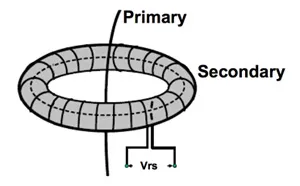
Figure 2: Schematic of a Rogowski coil.
Digital processing offers reliable performance over the long service life expected of typical smart meters and overcomes drift in analog components due to time and temperature that can lead to measurement errors. Analog components can also introduce slight phase shifts that require calibration. Digital integrators have consistent and accurate phase response. Declining cost and power consumption of high-speed 32-bit microcontrollers make digital integration increasingly feasible. A single meter design can be made compatible with either CTs or Rogowski coils by software selection, although integration increases processing load.
Although Rogowski coils are less susceptible to magnetic tampering than CTs, some methods can still affect the signal if not mitigated. The coil itself is affected by external magnetic fields, which can produce erroneous readings. Careful coil design to cancel external fields typically prevents magnetic tampering effectively. Another coupling mechanism that can affect the sensor is inductive coupling; a Faraday shield can be used to prevent this and to block capacitive coupling effects.
Capacitive Coupling and Shielding
There is a small capacitance between the secondary winding of a current sensor and the conductor or busbar passing through it. If the busbar is at high potential, the AC on that busbar can couple through the capacitance and affect the sensor output. Metal shielding around the sensor can reduce this influence but may not eliminate it. Some current sensors use a specially designed Faraday shield placed very close to the secondary winding. The shield prevents the AC on a high-voltage busbar from affecting the output, eliminating the effects of capacitive coupling.
Open-Form Sensors
Compared with CTs, Rogowski coils can be made openable. Without a metal core, coils can be fabricated as two hinged parts and clipped around a conductor instead of requiring the conductor to be separated. Many shapes and sizes are possible to accommodate busbars and round conductors.
Hall-Effect Sensors
A noncontact alternative is the Hall-effect sensor, although these typically do not offer the high accuracy of shunts, CTs, or Rogowski coils. Consequently, Hall-effect sensors are less often used in utility meters where billing accuracy is mandatory. They are finding applications in smart-grid systems where device-level energy monitoring is suitable, such as monitoring efficiency in data-center power systems or analyzing renewable-energy system performance.
Like Rogowski coils or CTs, Hall-effect sensors can be noncontact and do not require galvanic isolation. Unlike Rogowski coils, Hall-effect sensors provide direct DC measurements as well as AC. They are electronic devices that increasingly include on-chip signal preprocessing to present outputs compatible with the A/D converters of typical microcontrollers.
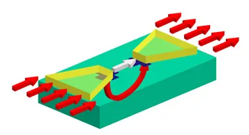
Figure 3: IMC structure concentrates magnetic flux onto the integrated Hall element.
An example is Melexis's MLX91205, a Hall-effect sensor designed for easy assembly near conductors. Standard CMOS processes are used to make the current sensor. An added ferromagnetic layer, called an integrated magnetic concentrator (IMC), is included in a simple post-processing step. The IMC amplifies the magnetic field and concentrates it on the Hall element. The IMC is a high-permeability, low-coercivity, amorphous ferromagnetic layer directly bonded to the surface of the Hall-sensor die. The IMC concentrates flux lines into the Hall element, which is roughly one-tenth the size of the IMC.
The two parts of the IMC collect and amplify magnetic flux parallel to the chip surface and locally rotate the in-plane component into a magnetic field perpendicular to the chip surface. Traditional Hall sensors are sensitive to fields normal to their surface, while IMC Hall sensors are sensitive to fields parallel to the surface.
IMC-Hall sensors are available in standard plastic SOIC-8 packages, so they can be placed on printed circuit boards using standard surface-mount equipment and reflow soldering. The measured current is either routed through a PCB trace directly under the sensor or the sensor can be mounted a short distance below a wired conductor or busbar.
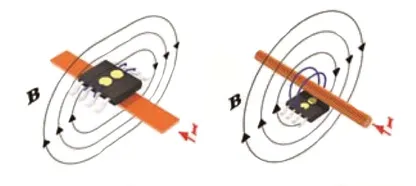
Figure 4: IMC Hall sensors can be mounted over a PCB current trace or beneath a wired conductor or busbar.
Sensor current range is limited by conductor and shield geometry. Increasing the cross-sectional area of the busbar or increasing the sensor-to-conductor distance will increase the range. These sensors can monitor currents from 5 A to 100 A on PCB traces, or up to 1000 A on busbars.
Outlook
As Hall-effect technology matures and on-chip processing becomes more capable, accuracy and current handling will improve over time, giving system designers more options as power measurement becomes more pervasive.