ALLPCB


If you're new to PCB design and wondering what IPC-2221 is, you're in the right place. IPC-2221 is a key industry standard that provides guidelines for designing reliable and safe printed circuit boards (PCBs). It covers everything from material selection to component placement and electrical spacing. In this beginner's guide, we'll break down the essentials of IPC-2221, explain its importance, and show you how to apply its requirements to your PCB projects. Whether you're just starting with PCB design or looking to understand IPC standards, this tutorial will help you build a strong foundation.
What Is IPC-2221 and Why Does It Matter?
IPC-2221, titled "Generic Standard on Printed Board Design," is a document created by the Institute of Printed Circuits (IPC), a global organization that sets standards for the electronics industry. This standard serves as a foundation for designing PCBs that are safe, reliable, and manufacturable. It provides detailed guidelines on various aspects of PCB design, ensuring that your boards meet quality benchmarks and perform as expected.
Why is IPC-2221 important for beginners? Without following a standard like this, your PCB design might face issues like electrical shorts, overheating, or manufacturing defects. By adhering to IPC-2221, you reduce risks and improve the chances of creating a functional product. For engineers and hobbyists, understanding this standard is a stepping stone to mastering PCB design basics.
Breaking Down the Core Elements of IPC-2221
IPC-2221 covers a wide range of topics related to PCB design. As a beginner, you don’t need to know every detail right away, but focusing on the core elements will help you get started. Below, we’ll explore the key areas this standard addresses and why they matter.
1. Material Selection for PCBs
Choosing the right materials is the first step in designing a PCB. IPC-2221 provides recommendations on substrate materials, such as FR-4 (a common fiberglass material), and copper thickness for conductive layers. For example, standard copper thickness is often 1 oz per square foot, which translates to about 35 micrometers. Using the wrong material or thickness can lead to issues like poor heat dissipation or weak mechanical strength.
For beginners, start with widely used materials like FR-4, which balances cost and performance. IPC-2221 ensures that your material choices meet industry norms, making your design compatible with most manufacturing processes.
2. Component Placement Guidelines
Where you place components on a PCB affects its performance and ease of assembly. IPC-2221 offers rules for spacing components to avoid interference and ensure proper heat distribution. For instance, high-power components like resistors or ICs should be placed away from heat-sensitive parts to prevent damage.
A practical tip for beginners is to group related components together. For example, place all power supply components in one area to minimize noise in signal paths. Following IPC-2221 guidelines helps you avoid common mistakes in layout planning.
Related Reading: Component Placement Rules for Surface Mount Technology (SMT)
3. Electrical Spacing and Clearance
One of the most critical aspects of IPC-2221 is its guidance on electrical spacing, also known as clearance and creepage distances. Clearance is the shortest distance through air between two conductive parts, while creepage is the shortest path along the surface of an insulating material. These distances prevent electrical arcing or short circuits, especially in high-voltage designs.
For example, IPC-2221 specifies that for a voltage of 100V, the minimum clearance between traces should be around 0.6 mm for external conductors. These values increase with higher voltages to ensure safety. As a beginner, always check the voltage requirements of your design and refer to the standard’s tables for exact spacing values.
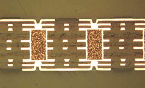
4. Trace Width and Current Carrying Capacity
Trace width determines how much current a PCB track can carry without overheating. IPC-2221 includes charts and formulas to calculate the appropriate width based on current, copper thickness, and temperature rise. For instance, a 10-mil (0.254 mm) wide trace with 1 oz copper can typically handle about 0.5 amps of current with a 10°C temperature rise.
For beginners, using online calculators that follow IPC-2221 can simplify this process. Ensuring proper trace width prevents failures like burnt traces and maintains the integrity of your design.
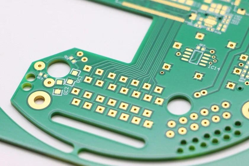
5. Via Design and Placement
Vias are small holes in a PCB that connect different layers. IPC-2221 provides rules for via size, spacing, and placement to ensure reliable connections. For example, a standard via might have a drill diameter of 0.3 mm and an annular ring (the copper around the hole) of at least 0.1 mm to maintain structural integrity.
As a beginner, avoid placing vias too close to each other or under components unless necessary, as this can complicate manufacturing. Following the standard ensures your vias are robust and functional.
Related Reading: Via to Via Spacing: IPC standards
Understanding IPC Standards: Why IPC-2221 Is Just the Start
While IPC-2221 is a foundational standard for PCB design, it’s part of a larger family of IPC standards that cover different aspects of electronics manufacturing. For instance, IPC-A-610 focuses on the acceptability of electronic assemblies, while IPC-7351 deals with surface mount design. As a beginner, starting with IPC-2221 gives you a solid base, but knowing about related standards can help as you grow in your skills.
These standards work together to ensure every stage of PCB production—from design to assembly—meets high-quality benchmarks. By understanding IPC standards as a whole, you’ll be better equipped to create designs that are not only functional but also easy to manufacture and assemble.
How to Apply IPC-2221 Requirements in Your First PCB Design
Now that you have a basic understanding of IPC-2221, let’s walk through how to apply its requirements in a simple PCB design project. Follow these steps to create a board that adheres to the standard and performs reliably.
Step 1: Define Your Design Goals
Start by outlining what your PCB needs to do. Are you designing a simple LED circuit or a more complex microcontroller board? Knowing the voltage, current, and component requirements will help you apply IPC-2221 rules effectively. For example, a low-voltage LED circuit might need minimal spacing, while a power supply board requires stricter clearance rules.
Step 2: Choose the Right Materials
Refer to IPC-2221 for material recommendations. For most beginner projects, a standard FR-4 board with 1 oz copper is a safe choice. This ensures good mechanical strength and conductivity without breaking the bank.
Step 3: Plan Your Layout
Use design software to place components according to IPC-2221 guidelines. Keep power components separate from sensitive signal paths, and ensure proper spacing between traces. Many design tools have built-in rules based on IPC standards, so enable these features to automate compliance.
Step 4: Calculate Trace Widths and Vias
Use IPC-2221 charts or online calculators to determine trace widths based on the current your circuit will carry. For a 1-amp current with a 10°C temperature rise, you might need a trace width of about 20 mils (0.508 mm) on 1 oz copper. Similarly, size your vias to handle the current without overheating.
Step 5: Double-Check Clearances
Before finalizing your design, verify that all clearances meet IPC-2221 requirements. For a 50V circuit, ensure a minimum clearance of 0.4 mm between external conductors. This step prevents electrical issues and ensures safety.
Common Mistakes Beginners Make with IPC-2221
Even with a standard like IPC-2221, beginners often make mistakes that can lead to design failures. Here are some common pitfalls and how to avoid them.
- Ignoring Voltage-Based Spacing: Failing to account for voltage differences between traces can cause arcing. Always check the standard’s clearance tables for your specific voltage levels.
- Overcrowding Components: Placing parts too close together can lead to heat buildup and assembly issues. Follow IPC-2221 spacing guidelines to give each component room to breathe.
- Using Incorrect Trace Widths: Underestimating current needs can cause traces to overheat. Use the standard’s charts to calculate the right width for your application.
By being aware of these issues, you can design PCBs that are safer and more reliable from the start.
Tips for Mastering PCB Design Basics with IPC-2221
As you grow more comfortable with IPC-2221, keep these tips in mind to improve your PCB design skills.
- Start Small: Begin with simple projects like a basic LED blinker to practice applying IPC-2221 rules before moving to complex designs.
- Use Design Tools: Leverage PCB design software with built-in IPC standards to automate compliance checks and reduce errors.
- Study Real Designs: Look at open-source PCB projects to see how experienced designers apply spacing, trace widths, and via rules in real-world applications.
- Stay Updated: IPC standards are periodically revised to reflect new technologies. Keep an eye on updates to ensure your designs remain compliant.
Why Following IPC-2221 Benefits Your PCB Projects
Adhering to IPC-2221 offers several advantages, especially for beginners. First, it ensures your designs are safe by preventing electrical and thermal issues. Second, it improves manufacturability, meaning your boards are easier to produce without costly errors. Finally, it builds credibility—following industry standards shows that you take quality seriously, which is important if you’re working with clients or collaborators.
For example, a PCB designed with proper IPC-2221 spacing can handle voltages up to 500V without risk of arcing, assuming clearances of around 2.5 mm are maintained for external conductors. This reliability can save time and money in the long run.
Conclusion: Start Your PCB Design Journey with IPC-2221
IPC-2221 is an essential standard for anyone stepping into the world of PCB design. By understanding its requirements for material selection, component placement, electrical spacing, trace width, and via design, you can create boards that are safe, reliable, and ready for manufacturing. This beginner’s guide has walked you through the basics of IPC-2221, offering practical steps and tips to apply its rules in your projects.
Whether you’re exploring PCB design for the first time or brushing up on industry standards, mastering IPC-2221 is a powerful way to build your skills. Start small, use the tools available, and refer to the standard as you grow. With this foundation, you’re well on your way to designing high-quality PCBs that meet professional benchmarks.