 ALLPCB


Introduction
Fuses serve as critical components in printed circuit board (PCB) designs, providing essential overcurrent protection PCB systems require to safeguard sensitive electronics from damage. In modern electronic applications, where power densities continue to rise, selecting the appropriate fuse current rating ensures circuits operate reliably under both normal and fault conditions. Engineers must grasp the principles behind fuse current rating calculation to avoid nuisance tripping or inadequate protection. This article explores fuse fundamentals tailored for PCB integration, offering a PCB fuse sizing guide that aligns with engineering best practices. By understanding these elements, designers can enhance system robustness and compliance with reliability standards. Key considerations include environmental factors and layout constraints unique to PCB environments.
What Is Fuse Current Rating and Why It Matters for PCBs
Fuse current rating defines the maximum continuous current a fuse can carry indefinitely without opening, typically specified at a standard ambient temperature of 25°C. This rating stems from the fuse element's material properties, such as a low-melting-point alloy or wire that heats up under overload, eventually melting to interrupt the circuit. For PCB applications, mismatches in fuse amp rating PCB can lead to catastrophic failures, including board-level fires or component destruction during short circuits. Overcurrent protection PCB demands precise sizing to handle steady-state loads while responding swiftly to faults. Industry relevance heightens in high-reliability sectors like automotive and medical devices, where downtime proves costly. Proper selection prevents thermal runaway in densely populated boards.
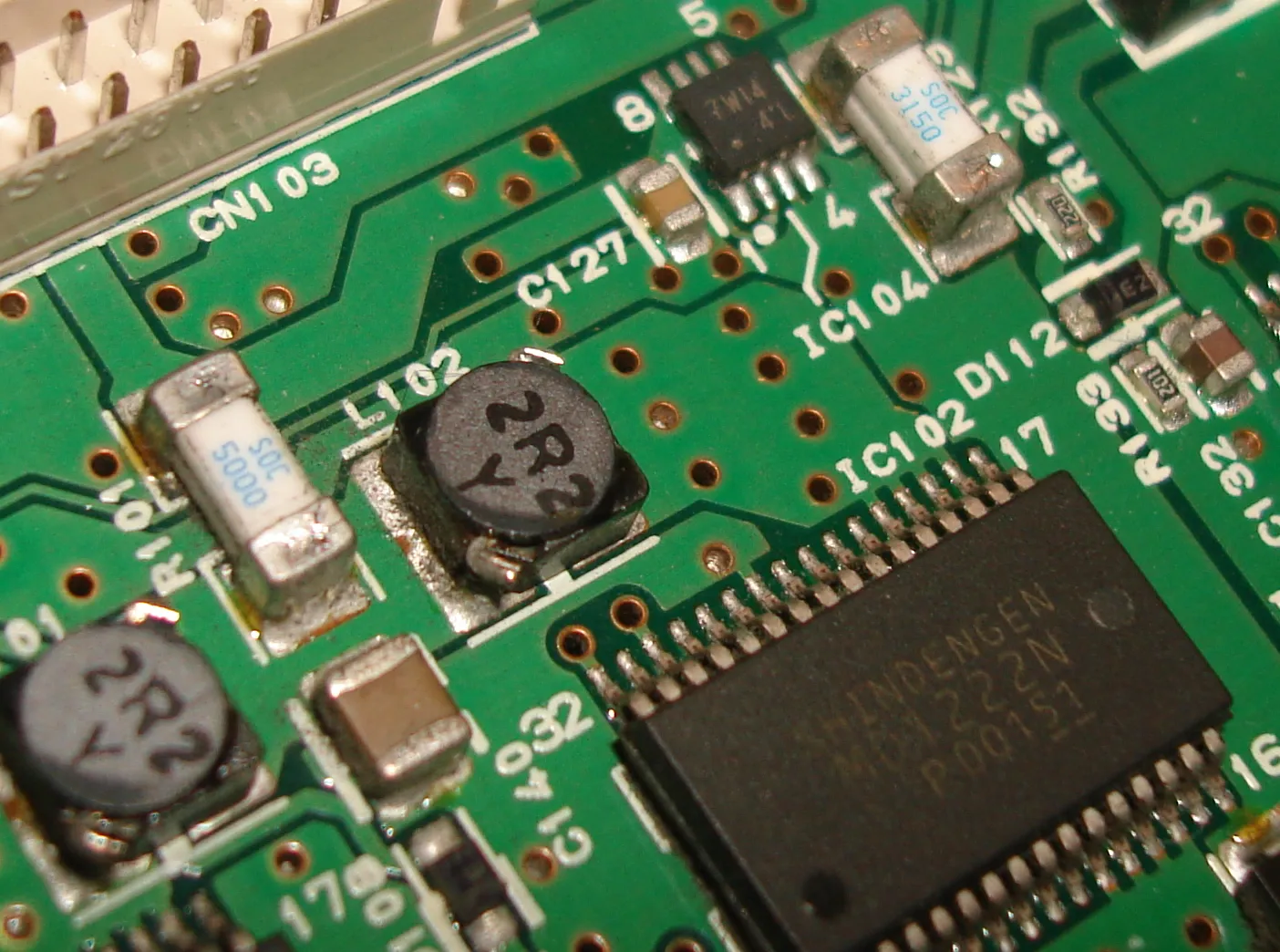
Fuses differ from circuit breakers by being non-resettable, making their one-time protection role permanent and thus demanding upfront accuracy in fuse current rating calculation. In PCBs, spatial limitations favor compact surface-mount device (SMD) fuses, but their ratings must account for proximity to heat-generating components. Ignoring this risks accelerated aging or false opens during inrush currents from capacitors. Engineers prioritize this metric to balance protection with operational continuity, ensuring the fuse holds under maximum expected loads with a safety margin.
Technical Principles of Fuse Operation in PCB Contexts
Fuses operate on thermal principles, where current-induced I2R heating raises the element temperature until it reaches the melting point, severing the circuit. Time-current characteristics (T-C curves) plot operating time against current multiples of the rating, distinguishing fast-acting fuses for transient-sensitive circuits from slow-blow types for motor startups or capacitive inrush. In PCB designs, these curves guide fuse current rating calculation by matching the application's fault profile. Breaking capacity, or interrupting rating, specifies the maximum fault current the fuse clears safely without exploding, crucial for low-voltage DC boards where arcs pose fire risks. Voltage rating must exceed the system's maximum to prevent sustained arcing post-melt.
PCB integration introduces unique challenges, as fuse body temperature interacts with board-level thermal profiles. Traces feeding the fuse must support the full rating without excessive voltage drop or heating, per guidelines in IPC-2152 for current-carrying capacity. Fuse derating for PCB environments accounts for elevated ambients from nearby power devices, reducing effective ratings nonlinearly above 25°C. Parasitic effects like solder joint resistance further influence performance, necessitating robust layout practices.
PCB Fuse Sizing Guide: Step-by-Step Calculation and Selection
Effective PCB fuse sizing begins with determining the circuit's steady-state current, including all loads under worst-case conditions like low battery voltage or high temperature. Apply a derating factor of 25% to 50% above this value to prevent nuisance openings, yielding the minimum fuse amp rating PCB. For example, a 2A load might warrant a 3A fuse, rounded to standard values like 2.5A or 3.15A. Incorporate inrush analysis using T-C curves to ensure the fuse withstands startup surges without premature action. Voltage and breaking capacity must exceed system maxima, often 50A to 150A for SMD fuses in 32VDC applications.
Trace sizing complements fuse selection, as per IPC-2221 guidelines on conductor widths to limit temperature rise to 10-20°C. Use PCB design tools to verify paths handle rated currents without hotspots. Fuse derating for PCB derating curves from datasheets adjust ratings for ambients up to 85°C, applying multiplicative factors like 0.8 at 50°C. Environmental factors such as altitude reduce air cooling, demanding further conservatism. Validate through simulation or thermal testing to confirm real-world margins.
Consider fault scenarios: short-circuit currents from capacitor discharge or semiconductor failure define the prospective peak. Slow-blow fuses suit inductive loads, while fast-acting protect precision analog sections. Placement away from ESD-sensitive areas and vias minimizes stress concentrations. Multilayer boards benefit from dedicated power planes feeding fuses for uniform current distribution.
Best Practices for Overcurrent Protection in PCB Design
Implement overcurrent protection PCB through layered strategies: primary fuses at power entry, secondary polyfuses for peripherals, and current-limiting resistors where feasible. Standardize fuse footprints for rework ease, adhering to J-STD-001 for soldering reliability. Thermal vias under SMD fuses dissipate heat, extending effective ratings in high-density layouts. Monitor board temperatures during qualification to refine derating applications.
Derating protocols prevent overloads in varying ambients; consult manufacturer curves rather than linear approximations. For high-current paths, parallel fuses distribute load but require synchronized characteristics. Documentation of calculations ensures traceability, aiding failure analysis. Integration with supervisory circuits like current sense amplifiers provides monitoring without compromising fuse autonomy.
Troubleshooting Common Fuse Issues on PCBs
Engineers encounter nuisance tripping from underrated fuses or underrated traces per IPC-2152 capacities. Inspect for solder bridges inflating inrush or poor joints adding resistance. Overheating signals inadequate derating for PCB hotspots; infrared imaging reveals culprits. Faulty protection arises from insufficient breaking capacity, exploding fuses during shorts. Iterative prototyping with varied ratings resolves these, prioritizing empirical data over simulations alone.
Conclusion
Mastering fuse fundamentals empowers engineers to implement robust overcurrent protection PCB designs. Fuse current rating calculation, informed by derating and trace sizing, forms the cornerstone of reliable systems. Adhering to principles like 25-50% margins and T-C curve matching ensures performance across lifecycles. PCB fuse sizing guides streamline selection, mitigating risks in compact electronics. Prioritize standards-compliant practices for enduring protection.
FAQs
Q1: How do you perform fuse current rating calculation for a PCB?
A1: Start with maximum steady-state current, add 25-50% margin for safety and inrush, then select the next standard rating. Cross-reference T-C curves against load profiles and apply ambient derating from datasheet graphs. Verify traces support the rating per IPC guidelines to avoid bottlenecks. This PCB fuse sizing guide prevents under- or over-protection effectively.
Q2: What is fuse derating for PCB applications?
A2: Fuse derating for PCB reduces rated current based on ambient temperatures above 25°C, using nonlinear curves to account for self-heating. High board densities amplify needs, often halving ratings at 85°C. Pair with wide traces and thermal relief for optimal performance. Essential for overcurrent protection PCB in enclosed systems.
Q3: Why is fuse amp rating PCB critical for overcurrent protection?
A3: Fuse amp rating PCB must exceed normal loads with margin to avoid nuisance blows while clearing faults swiftly. Undersizing risks fires; oversizing delays response. Balances reliability in power electronics, considering voltage drop and heat. Key to PCB fuse sizing guide success.
Q4: How does IPC-2152 influence PCB fuse sizing?
A4: IPC-2152 provides trace current capacities, ensuring paths to fuses handle full ratings without excessive rise. Guides width selection for given currents and thicknesses. Integrates into fuse current rating calculation for holistic protection. Prevents thermal failures in high-power designs.
References
IPC-2152 — Standard for Determining Current Carrying Capacity in Printed Board Design. IPC, 2009
IPC-2221B — Generic Standard on Printed Board Design. IPC, 2003
IEC 60127-4 — Miniature fuses - Part 4: Universal modular fuse-links. IEC, 2012


