 ALLPCB


Introduction
Vehicle electronics have become integral to modern automobiles, powering everything from engine control units to advanced driver assistance systems. Printed circuit boards serve as the backbone for these systems, handling complex signals and high currents under demanding conditions. Automotive fuses play a critical role in safeguarding these PCBs by interrupting overcurrent faults, preventing catastrophic failures that could compromise safety. Integrating fuses directly into PCB designs, known as automotive fuse PCB configurations, enhances compactness and reliability. This approach is essential for car fuse protection in environments exposed to vibration, thermal cycling, and electrical transients. Engineers must prioritize fuse selection and placement to ensure vehicle electronics operate without interruption.
As electric vehicles proliferate, the power demands on PCBs intensify, making robust protection strategies non-negotiable. Blade fuse PCB holders, in particular, offer a balance of accessibility and performance for automotive applications. Proper implementation not only meets regulatory expectations but also extends the lifespan of critical components. This article explores fuse types for cars, design principles, and best practices tailored for engineering precision.
What Are Automotive Fuses and Why They Matter in PCB Design
Automotive fuses are sacrificial devices designed to melt under excessive current, breaking the circuit and protecting downstream electronics. In PCB contexts, they provide targeted car fuse protection for modules like power distribution boards and sensor interfaces. Without fuses, short circuits or overloads could lead to thermal runaway, damaging vehicle electronics and risking fires. Their importance escalates in automotive settings due to the high reliability demands, where failures can affect drivability or safety systems.
Fuses differ from circuit breakers by being one-time use, which suits cost-sensitive automotive production. In PCB design, fuses enable modular protection, isolating faults without affecting the entire board. This modularity supports fault-tolerant architectures common in vehicle electronics. Standards like ISO 8820 define fuse-link specifications for road vehicles, ensuring interoperability and performance consistency across designs.
Engineers value fuses for their simplicity and fast response times, typically in milliseconds. Proper integration minimizes voltage drops and heat generation, preserving signal integrity.
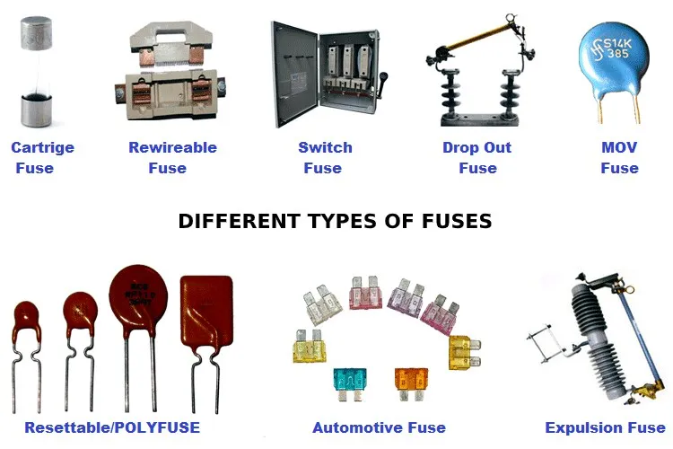
Common Fuse Types for Cars Suitable for PCB Mounting
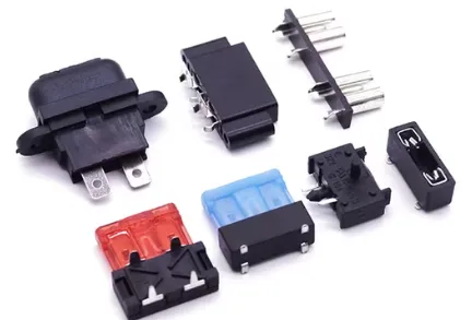
Fuse types for cars vary by current rating, physical size, and mounting method, with PCB-compatible options prioritizing space efficiency. Blade fuses dominate automotive use due to their standardized tabs and color-coded amperage identification, making them ideal for quick replacement. Standard blade fuses handle up to 30A or more, while mini and micro variants suit lower-power circuits in compact PCBs. These types integrate via through-hole holders soldered directly onto the board, forming reliable blade fuse PCB assemblies.
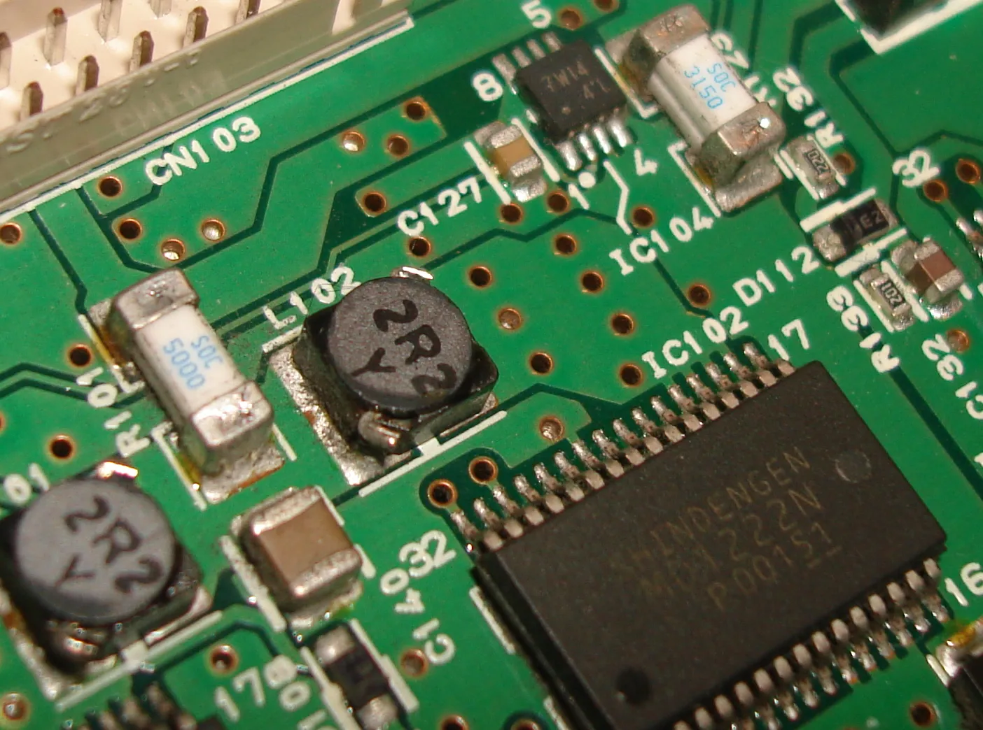
Surface-mount device fuses offer an alternative for high-density designs, soldering flat onto pads without holders. However, they require precise reflow processes and suit currents below 10A typically. Resettable polymeric positive temperature coefficient devices provide overcurrent protection that resets after cooling, useful for non-critical vehicle electronics. Each type balances protection speed, interrupt capacity, and environmental robustness.
- Standard Blade - Typical Application: Power distribution; PCB Mounting Style: Through-hole holder
- Mini Blade - Typical Application: Control modules; PCB Mounting Style: Through-hole or clip
- Micro Blade - Typical Application: Sensors; PCB Mounting Style: Surface-mount holder
- SMD Fuse - Typical Application: Low-power ICs; PCB Mounting Style: Direct pad solder
Selecting the right fuse type depends on expected load, fault currents, and board constraints. Blade fuse PCB setups excel in serviceability, allowing field replacement without specialized tools.
Technical Principles of Automotive Fuse PCB Integration
Fuse operation relies on a calibrated element that heats and severs under overcurrent, governed by I2t characteristics for energy withstand. In PCB design, engineers position fuses at power entry points to isolate faults early, minimizing exposed copper. Trace widths feeding the fuse must comply with IPC-2221 guidelines to handle nominal currents without excessive heating, preventing premature fuse blowing.
Clearance and creepage distances around fuses prevent arcing, especially under automotive humidity. Thermal management involves copper pours or vias to dissipate holder heat, avoiding reflow on nearby components. Vibration resistance demands secure mechanical retention, often with locking clips or epoxy potting.
Current derating by 25 to 50 percent accounts for ambient temperatures and aging, ensuring margin in vehicle electronics. Fuse holders contribute inductance, so short leads reduce EMI in high-frequency circuits. These principles form the foundation for robust automotive fuse PCB layouts.
Best Practices for Implementing Car Fuse Protection on PCBs
Start with schematic capture specifying fuse ratings slightly above maximum load, incorporating inrush considerations for capacitive loads. Layout fuses on the top layer near connectors, routing wide power planes directly to pads. Use IPC-6012DS qualification criteria for automotive rigid boards to validate thermal and mechanical endurance.
Soldering follows J-STD-001 requirements for through-hole components, emphasizing fillet formation and void-free joints. Post-assembly, apply conformal coating over holders to shield against contaminants. Testing includes overcurrent simulation, vibration per automotive profiles, and thermal shock to verify performance.
Multilayer boards benefit from dedicated ground planes under fuses for heat sinking. Documentation includes fuse replacement procedures and rating labels on the PCB silkscreen. These practices enhance reliability in demanding vehicle environments.
Challenges and Troubleshooting in Automotive Fuse PCB Designs
Mechanical stress from engine vibrations can loosen blade fuse PCB connections, leading to intermittent contact. Engineers mitigate this with strain relief and locking mechanisms. False tripping occurs from harmonic currents in switched-mode supplies, addressed by selecting time-delay fuses.
Overheating traces narrow for high currents violate design rules, causing nuisance opens. Troubleshooting involves oscilloscope checks for inrush spikes and thermal profiling. Environmental factors like salt spray demand sealed holders for under-hood placements.
Case in point: A power module PCB experienced repeated failures until trace widths were recalculated per IPC-2221, widening them by 50 percent. Post-fix, vibration tests confirmed stability. Systematic root-cause analysis resolves most issues efficiently.
Conclusion
Automotive fuses are indispensable for protecting vehicle electronics on PCBs, with blade fuse PCB and other types offering tailored solutions. Adhering to principles like strategic placement, proper trace sizing, and standards compliance ensures fault isolation without compromising performance. Best practices in layout, assembly, and testing address automotive rigors, from vibration to thermal extremes. Engineers achieve optimal car fuse protection by balancing protection speed, serviceability, and cost. Prioritizing these elements yields durable designs that support advancing vehicle technologies.
FAQs
Q1: What are the primary fuse types for cars used in PCB designs?
A1: Fuse types for cars include standard blade, mini blade, micro blade, and SMD variants, each suited to automotive fuse PCB needs. Blade types via holders provide high-current handling and easy replacement for power modules. SMD fuses fit dense layouts for sensors. Selection hinges on current, space, and environmental factors for reliable vehicle electronics protection.
Q2: How does blade fuse PCB integration enhance car fuse protection?
A2: Blade fuse PCB holders mount directly on boards, positioning protection close to power inputs for fast fault isolation. They support quick field servicing, critical for automotive maintenance. Proper design per IPC guidelines helps prevent thermal issues, ensuring vehicle electronics safety. This method also optimizes space in ECUs and distribution boards.
Q3: Why follow standards in automotive fuse PCB design?
A3: Standards like ISO 8820 and IPC-6012DS help ensure fuse performance and PCB durability in harsh conditions. They guide trace sizing, assembly, and qualification, reducing failure risks. Compliance aids certification and interoperability in vehicle electronics. Engineers rely on them for predictable overcurrent response and mechanical robustness.
Q4: What best practices improve reliability of vehicle electronics fuses on PCBs?
A4: Place fuses near power entries with wide traces, derate fuse ratings, and use vibration-resistant holders. Employ thermal vias to manage heat and conformal coating to protect joints. Test per automotive profiles to verify integrity. These steps deliver robust car fuse protection across operating conditions.
References
IPC-2221B — Generic Standard on Printed Board Design. IPC, 2003
IPC-6012DS — Qualification and Performance Specification for Rigid Printed Boards for Automotive Applications. IPC, 2015
ISO 8820 — Road vehicles — Fuse-links. ISO, 2015


