ALLPCB


Introduction
When people think of wearable devices, a smartwatch often comes to mind. Buying a fashionable smartwatch is an option, but makers can also build one from scratch. This DIY project, named RetroWatch, is based on Android and Arduino development boards. All software and hardware designs for the project are open source. The project supports u8glib, allowing a choice of various displays including OLED while reducing display RAM usage.
Step 1: System Architecture
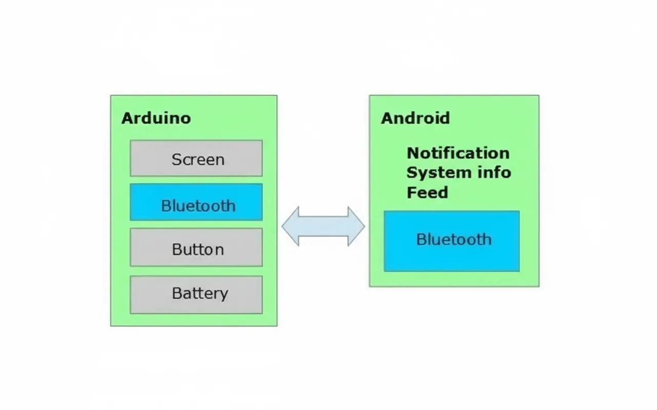
The RetroWatch architecture is simple. The hardware platform uses an Arduino with a single control button. An Android application connects to the watch via Bluetooth, allowing the watch to display RSS pushes and system notifications from the Android device.
Step 2: Components
Because this is a smartwatch, component compactness is critical.
Arduino Microcontroller
The chosen board is the compact Arduino Pro Mini, a lightweight version of the Uno R3. It lacks a USB interface chip, so a USB-to-UART module is required for programming. The Pro Mini comes in 3.3V and 5V versions; the 3.3V version was chosen because the Bluetooth module and display support 3.3V, and a 3.7V LiPo battery works well.
The 3.3V Pro Mini runs at 8 MHz; the 5V version runs at 16 MHz, and 8 MHz is sufficient for this project. The typical Pro Mini uses an ATmega328 microcontroller with 2 KB RAM; variants with only 1 KB RAM are insufficient for this project.
Bluetooth
The HC-06 Bluetooth module is common. Some HC-06 modules include an adapter board with a reset button and an LED but are larger. To save space and cost, a bare HC-06 module without the adapter board is used here.
Display
A small, low-power display is required. This project uses Adafruit's 0.96" 128×64 OLED, which supports I2C and SPI and connects easily to Arduino. The selected driver is the SSD1306 for I2C.
Battery
A 3.7V LiPo battery with 140 mAh capacity was chosen. Typical usage lasts about 7 hours. Battery physical size should be chosen to fit the enclosure.
Other Parts
In addition to wiring, a 10 kΩ resistor is needed for the button connection.
Step 3: Assembly
The hardware wiring is as follows.
Bluetooth to Arduino
- VCC → 3.3V
- GND → GND
- TX → D2
- RX → D3
OLED to Arduino (I2C)
- GND → GND
- VCC → VCC
- SDA → A4 (analog pin 4)
- SCL → A5 (analog pin 5)
If using SPI, connect according to Adafruit guidance:
- D1: MOSI → Arduino D11 (MOSI)
- D2: MISO → Arduino D12 (MISO) (optional)
- D0: CLK → Arduino D13 (SCK)
- DC: DC (data/command) → Arduino D8 (or other)
- CS: CS (chip select) → Arduino D10 (SS)
- RES: RESET → Arduino D9 (or other)
Button
Connect the button using a 10 kΩ resistor as shown in the schematic.
Battery to Arduino
- Positive → RAW
- Negative → GND
USB-to-UART Module to Arduino
- 3.3V → VCC
- TXD → RXD
- RXD → TXD
- GND → GND
Step 4: Compile Arduino Code and Upload
The Arduino project source is available on GitHub. Before compiling, configure your development environment.
Install Graphics Libraries
Install the Adafruit_SSD1306 and Adafruit_GFX_Library to display graphics on the OLED. In some environments these Adafruit libraries conflict with Robot_xxx libraries; if that occurs, back up and remove the Robot_xxx library from the libraries folder.
Warning: if your OLED uses the SH1106 driver, download the Adafruit_SH1106 driver from GitHub.
The project also supports u8glib; you can download the Arduino-supported version from the u8glib site.
Copy Bitmap Header
Copy the bitmap.h file from the RetroWatchArduino folder into Arduino/hardware/libraries/RetroWatch under your Arduino installation. Create the path if it does not exist.
Modify Source Code
Open the Arduino IDE and load RetroWtchArduino.ino. If your pin assignments differ from this tutorial, modify the pin definitions accordingly. Example lines are shown below; Chinese comments inside the code have been translated to English.
SoftwareSerialBTSerial(9,8);// Bluetooth TX,RX connection pins
intbutton [Pi] n=5;// button pin
display.begin(SSD1306_SWITCHCAPVCC,0x3C);// OLED I2C address, replace Ox3D with your address
If you use u8glib, load RetroWatchArduino_u8glib.ino and note these lines:
U8GLIB_SSD1306_128X64u8g(U8G_I2C_OPT_NONE|U8G_I2C_OPT_DEV_0);// Modify according to the display you choose
SoftwareSerialBTSerial(2,3);// Bluetooth TX,RX connection pins
intbuttonPin=5;// button pin
If you use Adafruit libraries and the OLED reset pin, connect the OLED reset to Arduino D8 or another pin as defined in the code. Example code lines from the original source are shown below:
#defineOLED_RESET8
Adafruit_SSD1306display(OLED_RESET);
Compile and Upload
After completing the above steps, compile and upload the sketch. On success, the display will show the RetroWatch and Adafruit logos, then display 00:00.
Step 5: Android App and Source
Android versions from 4.3 onward support reading notifications from apps. Ensure the Android device runs Android 4.3 or later. For devices below 4.3, a limited version of the app can receive notifications on the watch but cannot read notification content.
The Android app source is available on GitHub. The app can also be installed from Google Play (RetroWatch or RetroWatchLE for older systems). After installing, grant the app permission to read notifications.
Enable Bluetooth on the phone and pair the Android device with the Arduino Bluetooth module. In the RetroWatch app, select the paired Arduino device; a display of "Connected" indicates success.
Use the app menu to select Data transfer to Watch to push time and messages to the smartwatch over Bluetooth.
Because of the watch hardware limits, many functions are implemented in the Android app; the watch mainly displays data. The app can configure which push messages (English characters only) and status notifications (phone battery and signal strength, etc.) are sent, and can subscribe to RSS feeds such as weather RSS to show weather on the watch. Updates synchronize every 30 minutes.
The app provides 65 different display icons; users can customize which icons are used.
Step 6: Watch Features
After installation, the watch operates in the following modes:
- Boot screen: shows logos during startup.
- Clock display: shows time from the connected Android phone. Clock display can be analog, digital, or hybrid. Pressing the button enters the emergency message display mode. If no updates or interactions occur for 10 minutes, the display switches to standby mode.
- Emergency message display: activated by a button press or when a new emergency message arrives. Press the button to view the next message; if there is no action for 10 seconds the watch automatically advances to the next message. After emergency messages are shown, the watch returns to normal message display. Due to 2 KB RAM, the watch stores up to 3 emergency messages; older messages are deleted when the limit is exceeded.
- Normal message display: after emergency messages, normal messages are displayed. Press the button or wait 5 seconds to advance. After messages are shown, the watch returns to clock display. Up to 7 normal messages are stored.
- Standby display: if no updates or interactions occur for 10 minutes, the watch switches to standby. In standby, only indicators (selectable in the Android app) and time in hh:mm format are shown, reducing power consumption. Pressing the button or receiving a new message returns the watch to clock display.
Step 7: Case and Enclosure
You can craft a simple enclosure by hand, download 3D files to print a custom case, or repurpose the device as a desktop notifier instead of wearing it.