 ALLPCB


Overview
Designing and implementing an optical heart rate monitoring (HRM) system, also known as photoplethysmography (PPG), is a multidisciplinary task. Design considerations include ergonomics, signal processing and filtering, optical and mechanical design, low-noise signal reception circuits, and low-noise current pulse generators. A recent technical article from Silicon Labs described optical design principles, key considerations, and requirements for integrated components used in HRM systems.
Heart Rate Monitoring in Wearables
Heart rate monitoring has become a common feature in wearable electronics. Manufacturers increasingly add HRM functions to health and fitness products, and integration is driving down sensor cost. Many HRM sensors now include several discrete components inside a highly integrated module, such as an analog front end (AFE), photodetectors, and light-emitting diodes. These modules reduce complexity and cost when adding heart rate monitoring to wearable products.
Form factors for wearables have evolved. Chest straps have long served the health and fitness market, but optical HRM is now widely used in wrist-worn devices. Advances in optical sensing technology and high-performance, low-power processors have enabled wrist-worn designs; heart rate algorithms have also improved to levels acceptable for wrist-worn products. Other wearable form factors are emerging, including headbands, fitness apparel, and ear-worn devices, but the primary application domain for physiological monitoring remains the wrist.
Integration and Accuracy Considerations
No two HRM applications are identical. System designers must balance many trade-offs, including product comfort, sensing accuracy, system cost, power consumption, sunlight interference, handling a variety of skin types, motion artifacts, development time, and physical size. These factors influence whether to adopt a highly integrated module or a design that uses more discrete components.
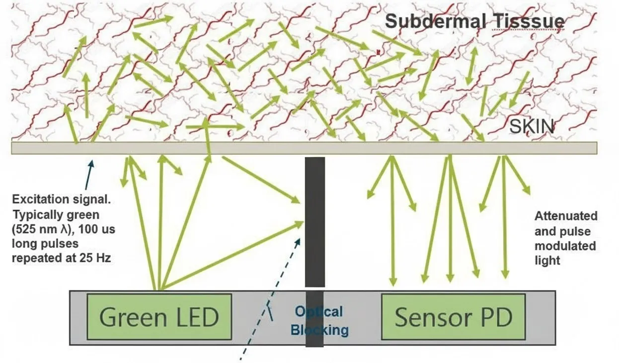
Basic Optical PPG Principle
Figure 1 shows the basic method for measuring heart rate signals using an optically derived PPG waveform. Light injected into tissue is modulated by capillary dilation and contraction caused by the cardiac pressure wave. Green LEDs are commonly used to inject light into tissue; the received signal is heavily attenuated by skin and detected by a photodiode. The photodiode output is sent to an electronic subsystem where the pulse-derived amplitude modulation is detected, filtered to remove motion noise, analyzed, and displayed.
One common system approach uses a custom microcontroller (MCU) to control pulsed LED drive signals and to read current output from a discrete photodiode. The photodiode current must be converted to voltage for an analog-to-digital converter (A/D). The current-to-voltage converter produces a reference voltage when photodiode current is zero, and the voltage drops as current increases.
LED Drive and Photodiode Considerations
Current pulses used in HRM systems typically range from 2 mA to 300 mA, depending on skin tone and the signal level required to overcome ambient sunlight. Infrared in sunlight is only weakly attenuated by tissue compared with green light, so sunlight can swamp the green PPG signal unless the green light is very strong or an expensive infrared-blocking filter is used.
Typically, the intensity of green LED light entering the skin ranges from 0.1x to 3x ambient sunlight. Due to severe tissue attenuation, the signal reaching the photodiode is very small, so the system needs just enough drive current to achieve a usable 70-100 dB signal-to-noise ratio (SNR), even assuming ideal, noise-free amplifiers and A/D converters.
The photodiode sizes used in designs range from 0.1 mm2 to 7 mm2. However, areas larger than about 1 mm2 can produce unreliable results under sunlight interference.
Costly and challenging modules in such systems include a fast, high-current voltage-to-current converter to drive LEDs; a current-to-voltage converter for the photodiode; and an MCU to run algorithms and process the sampled signals. A low-current LED driver configurable down to about 2 mA that can also generate very narrow pulses as short as 10 μs and a low-noise, high-SNR LED driver capable of up to 300 mA are expensive to implement from discrete components.
Short optical pulses on the order of 10 μs help the system tolerate motion and sunlight. A typical approach is a rapid optical test at 25 samples per second where each measurement includes one read with the LED off and one with it on. The difference removes ambient light influence and yields an optical measurement that is robust against flickering background light.
Very short pulses allow the LED peak intensity to exceed sunlight levels, which helps prevent the PPG carrier from being overwhelmed by ambient light. If ambient sunlight is larger than the PPG carrier, subtraction can remove the DC component, but arm motion introduces difficult-to-remove noise. Designers therefore use a combination of low-drive LEDs and appropriately sized photodiodes to balance motion and sunlight noise.
Integration Options
Many desired HRM features can be implemented through upfront design and integration into a single device. Integrating most of the circuitry onto a single chip enables relatively small packages, for example a 3 mm x 3 mm package, and can even include the photodiode.
Examples of Integrated Modules
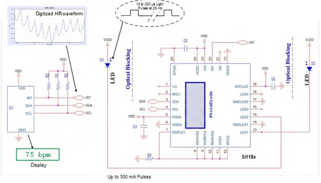
Figure 3 shows an integrated HRM sensor approach that requires only external LEDs. This approach supports high-performance heart rate detection while allowing engineers to focus on the optical interface between the PCB and the skin.
For even smaller solutions, LED die and control circuitry can be integrated into the same package with optical components such as lenses to improve LED output. Figure 4 shows a highly integrated sensor module that includes all required components. Such a module does not require external LEDs because LEDs and photodiodes are integrated within the module, which can be mounted directly beneath the optical interface, for example under the back cover of a smartwatch. The reduced distance between LEDs and photodiodes lowers light loss through tissue and enables very low-power operation.
Integrating multiple LEDs also addresses optical leakage between LEDs and the photodiode, eliminating the need for light-blocking structures on the printed circuit board such as plastic or foam inserts and specialized copper layers.
Algorithms and Development Options
Heart rate algorithms are a significant part of the design effort. Motion during exercise degrades the signal and can generate artifacts that mimic true cardiac signals. If a product team lacks algorithm development resources, third-party providers can license algorithms. Silicon Labs offers heart rate algorithms for its sensor families that can be compiled and run on many host processors.
Ultimately designers must decide the appropriate level of integration for a given HRM application. Teams can simplify design and accelerate time to market by choosing highly integrated modules and licensed algorithms. Teams with deep optical sensing expertise and sufficient time and resources may prefer discrete sensors, photodiodes, lenses, and custom system integration, and may develop their own heart rate algorithms.


