ALLPCB


Overview
Beyond ubiquitous consumer smartphones, 5G wireless links can serve a wide range of embedded applications such as IoT, machine-to-machine links, smart grid, vending machines, gateways, routers, security, and remote monitoring. The transition to 5G will not happen overnight. This requires antennas at the front end of wireless links that can support both 5G and legacy 2G/3G/4G bands. Even as 5G deployments grow rapidly, those legacy links will coexist for years.
For these reasons, engineers designing products must consider supporting legacy bands in addition to 5G bands. Even if the RF front ends or power amplifiers for each band differ, using a broadband antenna that serves both 5G and legacy bands offers practical benefits.
This article uses Abracon LLC illustrative devices to examine broadband antennas that cover low-band 5G spectrum and legacy bands. It shows how both visible external units and embedded modules can simplify design and the bill of materials, and help accelerate upgrade installations to 5G when required.
Start with regulatory bands
An antenna is the final element in the RF transmit path and the first element in the complementary receive path. Its function is to act as a transducer between the circuit world of currents and voltages and the RF world of radiated energy and electromagnetic fields.
When selecting an antenna for a target application, remember that the antenna's behavior does not depend on the modulation type or the industry standard being used. Parameters used to choose an antenna include center frequency, bandwidth, gain, rated power, and physical size, but none of these depend on whether the antenna will carry amplitude, frequency, or phase modulation (AM, FM, PM) or protocols such as 3G, 4G, 5G, or proprietary formats.
System designs that support 5G currently receive substantial attention, especially for sub-6 GHz 5G bands where most initial activity is concentrated. It is important to separate the wireless standards that a system supports from the frequencies and spectrum that determine antenna selection.
New 5G standards both exploit previously unavailable spectrum and use higher-order modulation schemes in existing spectrum to achieve higher throughput. Thus, even if industry support for older standards declines over time (for example, 3G in recent years), the spectrum used for those standards will continue to be reused by 4G and 5G allocations (see Figure 1).
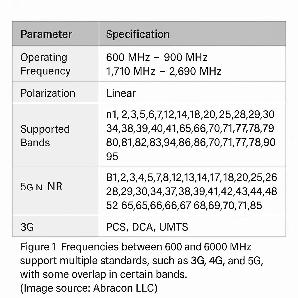
This means antennas that support 3G or 4G bands may still be suitable for 5G, and vice versa. Standards may become deprecated, yet the corresponding antennas can remain forward- and backward-compatible. Reusing antennas that support multiple standards and bands is often practical and desirable.
Other important standards within the 600 MHz to 6 GHz RF spectrum include:
- CBRS (Citizens Broadband Radio Service), spanning 3550 MHz to 3700 MHz (3.55–3.7 GHz), with a 150 MHz lightly regulated band. In the United States the FCC has designated shared access among incumbent users, Priority Access License (PAL) users, and General Authorized Access (GAA) users.
- LTE-M, short for LTE Cat-M1 (commonly called Cat M), a long-term evolution (4G) category that enables low duty-cycle, battery-powered IoT devices to connect directly to 4G networks without a gateway.
- NB-IoT (narrowband IoT), a cellular-level wireless technology using OFDM within the 3GPP framework to support very low data-rate, battery-powered devices that need mobile network connectivity.
Note on terminology: “wideband” generally refers to an antenna whose bandwidth is a substantial fraction of its center frequency, informally at least 20–30% of the center frequency. “Multiband” describes an antenna designed to support two or more regulatory bands; those bands may be closely spaced or widely separated. A multiband antenna may or may not be a wideband design.
Regardless of the number, spacing, or bandwidth of supported bands, a multiband antenna typically has a single RF connection even if internally it combines two or more elements. Unlike some simple wideband antennas, multiband designs may intentionally leave gaps in gain coverage across the overall range to minimize co-channel interference.
Embedded versus external antennas
Wireless standards are not directly an antenna design concern, but frequency and bandwidth influence physical implementation and thus are key design considerations. One major decision is whether to use an external antenna or an embedded antenna within the final product.
Embedded antennas have these attributes:
- They enable sleeker enclosures with no external protrusions that might break or snag.
- They remain permanently connected and available.
- They impose inherent limits on coverage, efficiency, radiation pattern, and other performance metrics.
- Their performance is affected by nearby circuitry, so placement is tightly linked to PCB size, layout, components, and overall arrangement.
- User hands or bodies may alter antenna patterns and performance.
By contrast, external antennas offer:
- More design freedom to tailor radiation pattern, bandwidth, and gain.
- Optimal placement via coaxial cable separation from the RF unit.
- Less impact from product design and enclosure electrical characteristics.
- Multiple form factors and configurations.
- A connection point such as a connector or cable, which can be a potential failure point.
The choice between external and embedded antennas depends on final application, user expectations, performance tradeoffs, and whether the device is mobile or fixed. For example, a smartphone with an external antenna could be perceived as a poor design choice, while a fixed IoT node with an external, optimally positioned antenna can offer more stable connectivity.
Benefits of multiband antennas
Multiband antennas meet current application needs while protecting future upgrades to new standards such as 5G. Why choose them if installation parameters are known? Key advantages include:
- One antenna can serve a product family across different bands, simplifying inventory and procurement.
- Embedded multiband antennas enable smaller form factors; external multiband antennas reduce the number of antenna connectors on the enclosure.
- They support IoT devices that may later upgrade to new bands for performance or because legacy bands are retired.
- A single external antenna for multiple bands preserves installation technique and tooling commonality.
- For fixed and critical mobile applications, RF subsystems can support dual-band operation to dynamically switch between bands for optimal performance at a given location.
- Designers can reuse a single embedded multiband antenna across unrelated products and benefit from prior modeling, placement, and manufacturing experience.
Real-world multiband antenna examples
Multiband antennas come in various sizes and termination types. The following examples illustrate this diversity.
AEBC1101X-S is a 5G/4G/LTE cellular whip antenna, 115 mm long with a maximum diameter of 19 mm, designed to operate from 600 MHz to 6 GHz. It uses a standard male SMA connector that can rotate 90° for direct mounting on enclosures, and can also be used with coaxial extension cables; reverse-polarity SMA is also available.
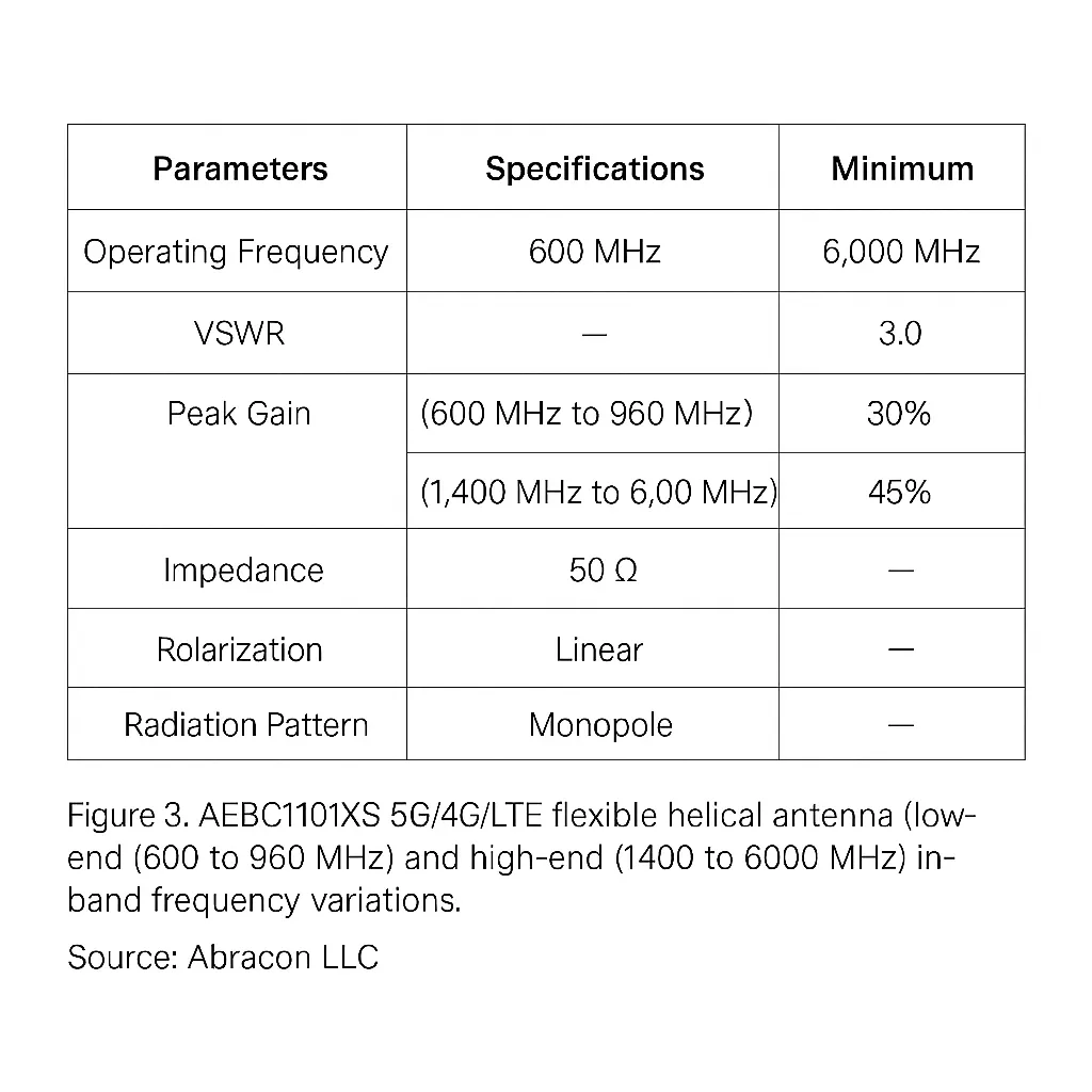
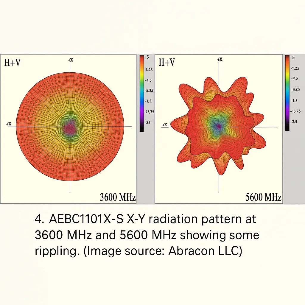
The radiation pattern is nearly circular over the band, with minor lobes at 3600 MHz and more pronounced lobes at 5600 MHz.
AECB1102XS-3000S is a 5G/4G/LTE/NB-IoT/CAT blade antenna covering 600 MHz to 6 GHz, sized 115.6 mm × 21.7 mm with a slim 5.8 mm thickness (Figure 5). It is designed for tape mounting on flat surfaces for simple installation.
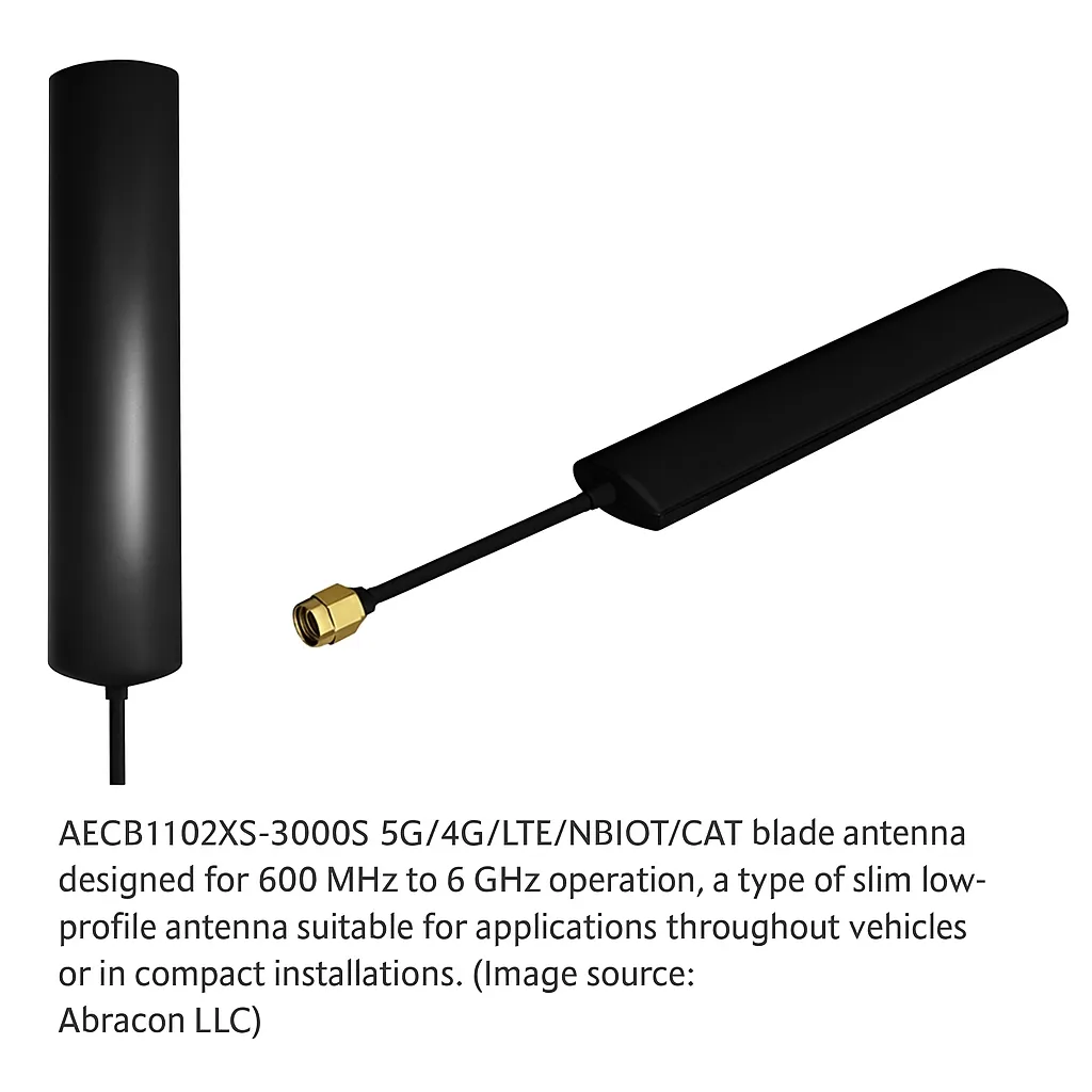
Its RF performance is similar to the AEBC1101X-S, with maximum VSWR below 3.5 and a peak gain of about 2 dBi, slightly below omnidirectional radiators. The X-Y and X-Z plane patterns are more complex.
A notable difference between AEBC1101X-S and AECB1102XS-3000S is termination. The blade unit ships with a 1 m LMR-100 coaxial cable (replacing RG174 and RG316 types) and a male SMA connector. Other cable lengths and connector types beyond SMA are available as standard options for flexible connectivity.
ACR4006X is a 600–6000 MHz wideband ceramic patch antenna in an SMD package sized 40 × 6 × 5 mm. It requires a small LC impedance-matching network consisting of an 8.2 nH inductor and a 3.9 pF capacitor (both 0402) to achieve 50 Ω (Figure 8).
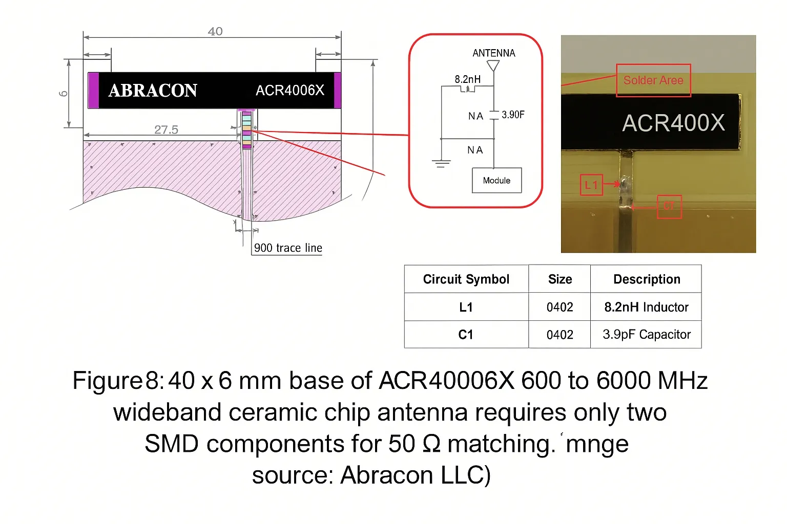
The datasheet lists ACR4006X as a 600–6000 MHz device, but note the efficiency, peak gain, and average gain plots show intentional gaps. The antenna is optimized for three specific bands within that range: 600–960 MHz, 1710–2690 MHz, and 3300–6000 MHz, supporting 3G, 4G, 5G allocations and several smaller spectrum blocks.
ACR4006X is not intended for GPS reception, so no specified performance is given at GPS carrier frequencies 1575.42 MHz (L1) and 1227.6 MHz (L2).
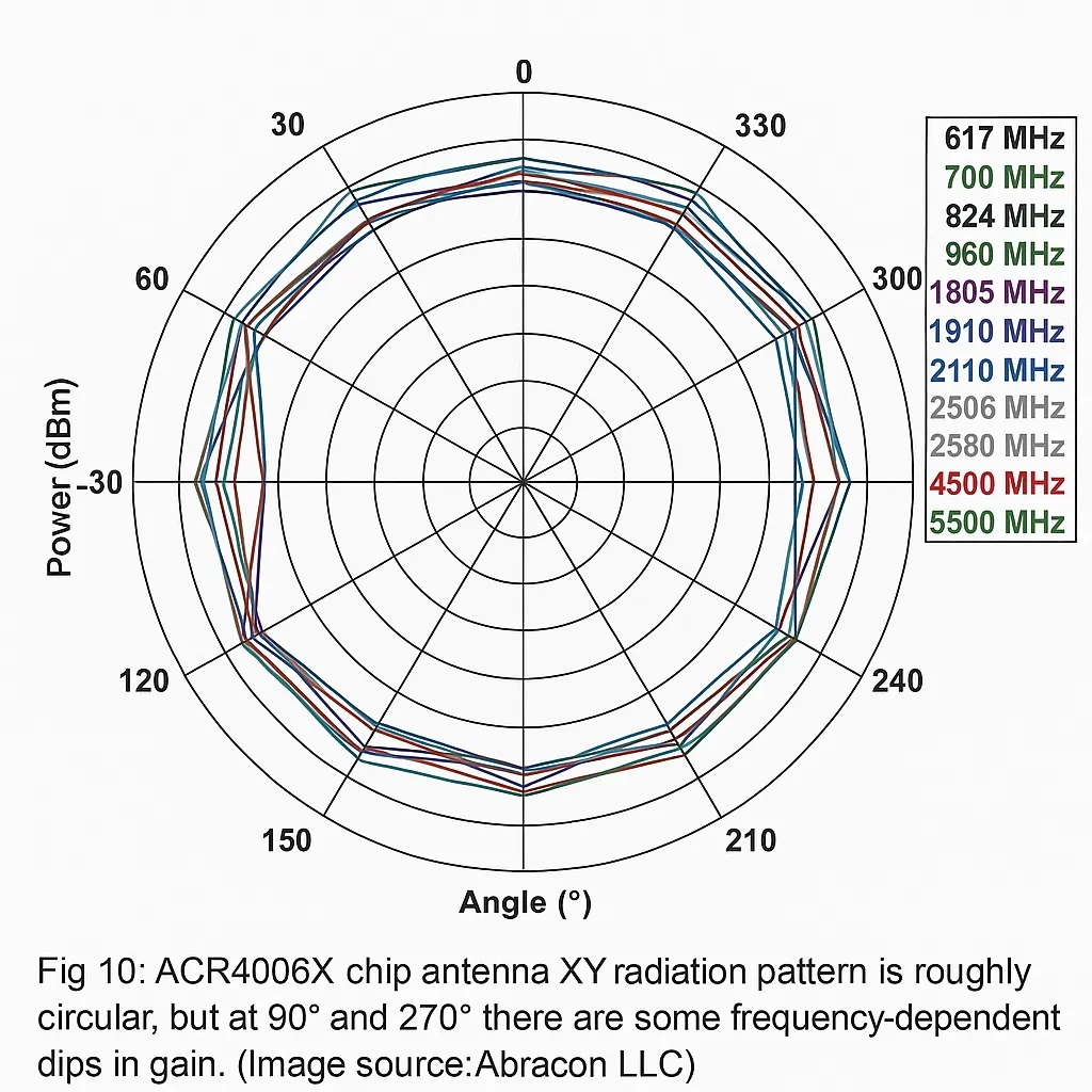
The X-Y radiation pattern of ACR4006X varies with frequency but remains roughly circular over the broadband, with moderate gain dips at 90° and 270° in the low-frequency range (Figure 10).
Evaluation and testing
Evaluate antenna performance starting with the datasheet, verify in an anechoic chamber, and conclude with field testing using the final product. For external antennas, enclosure, user body, antenna location, and placement markedly affect real-world performance; internal PCB layout has less impact.
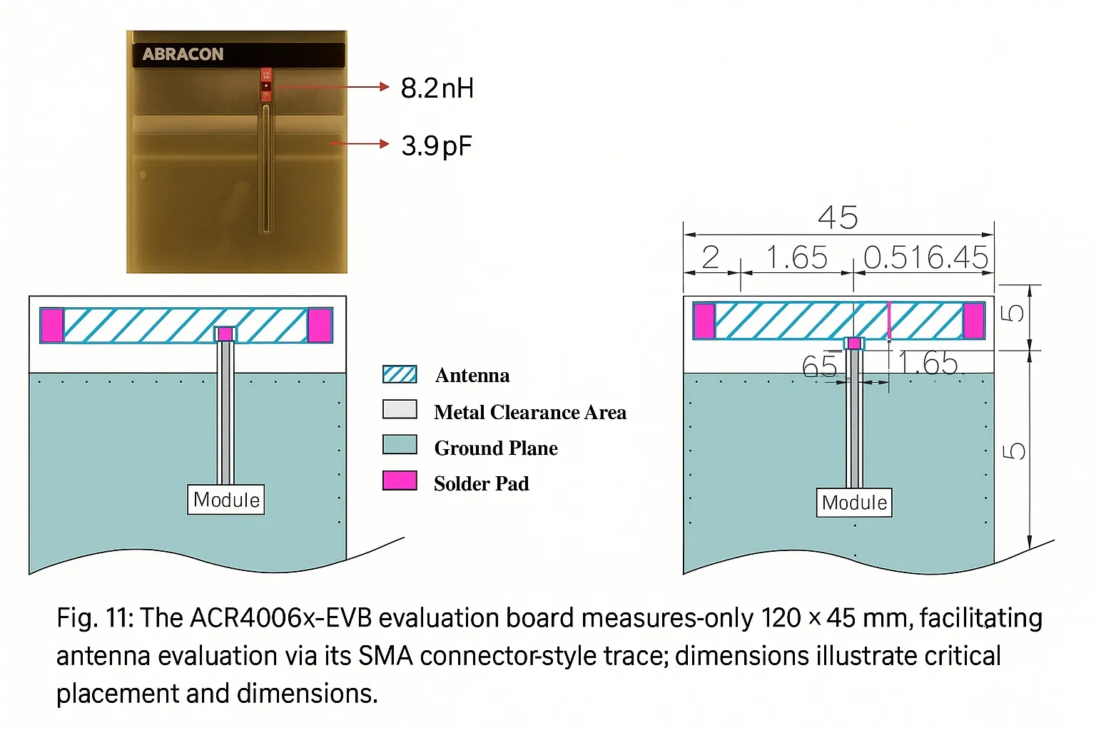
By contrast, the performance of embedded units like the ACR4006X ceramic patch is strongly influenced by nearby components and the PCB. To accelerate evaluation, Abracon provides the ACR4006X-EVB evaluation board for antenna engineering assessments.
The evaluation board is used with a vector network analyzer (VNA). After initial calibration, the antenna is assessed via the board's SMA connector and the VNA's calibrated port.
The EVB measures precisely 120 × 45 mm to facilitate correct antenna placement and includes the required 45 × 13 mm metal/ground clearance area around the antenna for normal operation (Figure 11).
Conclusion
Multiband antennas address many challenges faced by IoT devices, especially those that must support a legacy band today while providing smoother upgrade paths to newer standards such as 5G. They enable systems to support multiple bands to optimize performance in areas where a single band cannot guarantee connectivity. Embedded antennas mounted on a PCB allow sleeker enclosures, while external antennas with integrated RF connectors or coaxial cable attachments offer flexible placement for optimal signal paths.